XP Type II 工程师培训手册 (2.0).pdf.pdf - 第164页
FK-9F98-34 XP T ype II Series T raining T ext for Service Engineers Edition 2.0 XP242E – Chapter 6 Proper Data Mea surement s Page 9 of 30 5. Select [Maintenance C] – [Custom Maintenance] and the following prompt appears…
FK-9F98-34 XP Type II Series Training Text for Service Engineers
Edition 2.0 XP242E – Chapter 6 Proper Data Measurements Page 8 of 30
Camera Position Adjustment
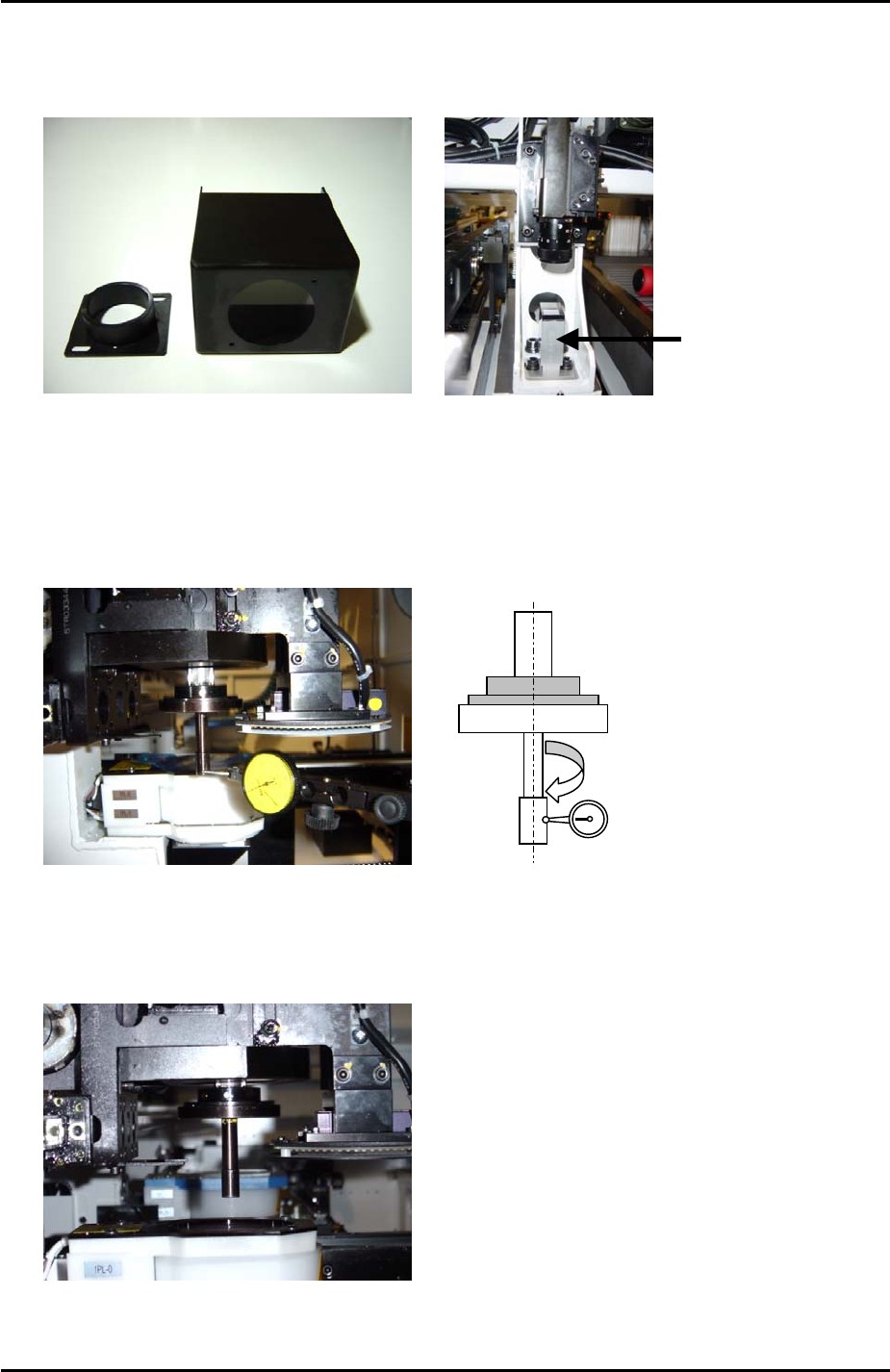
1. Remove the prism covers from the small prism:
Prism Covers
Small
Prism
2. Select [Maintenance A] – [I/O check] – [Y021 Nozzle UnHold] – [OFF] and attach
the nozzle jig (Z9531DEPJ0070) to the placing head.
3. Set the concentricity of the nozzle jig to within 0.05mm. This is to ensure the
nozzle jig is in the center of the placing head.
Use a dial gage
to measure the
concentricity.
Tolerance is
0.05mm.
4. Bring the nozzle jig above the center of the side 1 light source unit. Use a ruler to
check that it is directly above the center.
Nozzle jig is
directly above the
center of the light
source
Fuji Machine Mfg. Co., Ltd. Okazaki.
SMT Equipment Quality Assurance Dept.
6 – 8 CS Section
FK-9F98-34 XP Type II Series Training Text for Service Engineers
Edition 2.0 XP242E – Chapter 6 Proper Data Measurements Page 9 of 30
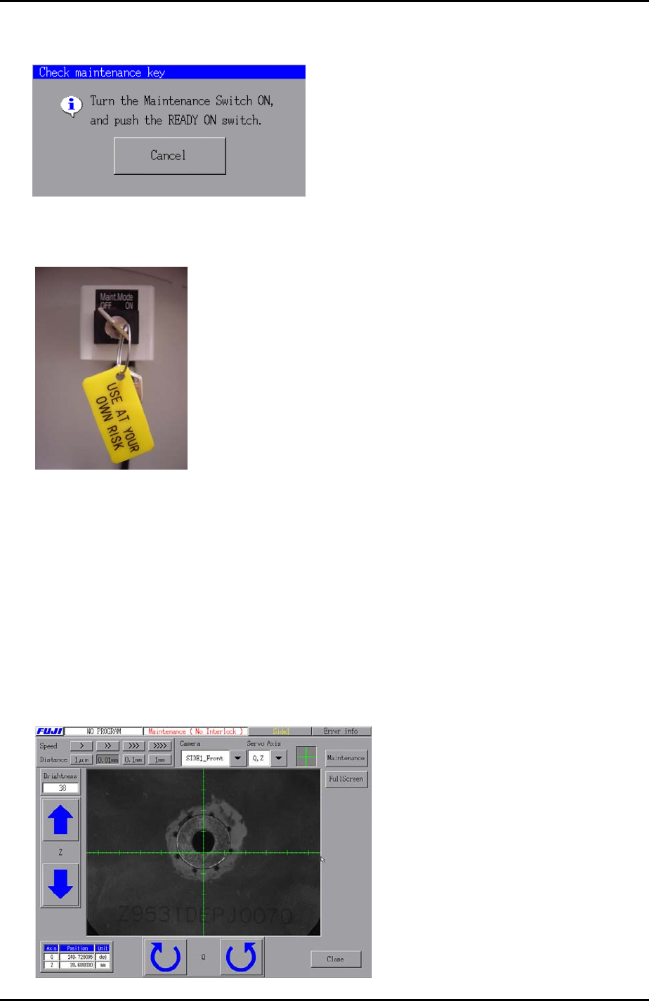
5. Select [Maintenance C] – [Custom Maintenance] and the following prompt appears
on the display:
6. Turn the Maintenance Mode key switch from OFF to ON.
7. Push the [READY ON] button.
Horizontal Cross Hair
1. Select “SIDE1_Front” from the [Camera] drop down list and select the cross hairs.
2. Use the inching keys to set the Z-axis to the part inspection height: (Z0 + 27.5mm).
3. An image similar to the one below should be on the display. Notice that the
horizontal cross hair is not yet in the center of the nozzle jig.
Fuji Machine Mfg. Co., Ltd. Okazaki.
SMT Equipment Quality Assurance Dept.
6 – 9 CS Section
FK-9F98-34 XP Type II Series Training Text for Service Engineers
Edition 2.0 XP242E – Chapter 6 Proper Data Measurements Page 10 of 30
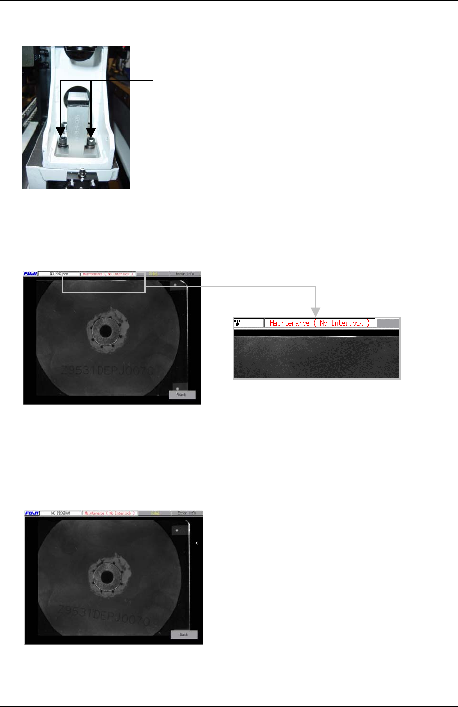
4. Adjust the position of the small prism so that the horizontal cross hair comes to the
center of the nozzle jig.
Loosen these bolts and adjust
the position of the small prism.
5. Once the horizontal cross hair is in the center of the nozzle jig select [Full Screen]
to display the whole image. If the nozzle is not exactly in the center of the light
source unit, the top or bottom edge of the image will be white as illustrated in the
photo below:
6. If the top or bottom edges of the image are white use the Y axis inching keys to jog
the position of the nozzle jig very slightly and then re-adjust the position of the small
prism so that the horizontal cross hair is in the center of the nozzle.
7. Select [Full Screen] and check that the top and bottom edges of the image are not
white, as illustrated in the photo below:
8. Also check that the holes around the nozzle jig are evenly balanced.
Fuji Machine Mfg. Co., Ltd. Okazaki.
SMT Equipment Quality Assurance Dept.
6 – 10 CS Section