XP Type II 工程师培训手册 (2.0).pdf.pdf - 第173页
FK-9F98-34 XP T ype II Series T raining T ext for Service Engineers Edition 2.0 XP242E – Chapter 6 Proper Data Mea surement s Page 18 of 30 7. Select [Maintenance A] – [Scale Setting] and make sure the 200V power supply …
FK-9F98-34 XP Type II Series Training Text for Service Engineers
Edition 2.0 XP242E – Chapter 6 Proper Data Measurements Page 17 of 30
6.9 Parts Camera Resolution
1. Equipment: glass gage for resolution measurement (Z3502DFAJ0020)
2. Select [Maintenance A] – [I/O Check] – [Y021 Nozzle Unhold] – [OFF] and attach a
20mm nozzle to the placing head.
3. Select [Maintenance A] – [I/O Check] – [Y020 Parts Pickup] – [ON] and attach the
glass gage to the placing head with the printed surface facing downwards.
4. Select [Maintenance C] – [Custom Maintenance] and move the Y-axis to the prism
position, and the Z-axis to the part inspection height: Z0 + 27.5mm + 2.5mm
(2.5mm is equivalent to the thickness of the glass gage).
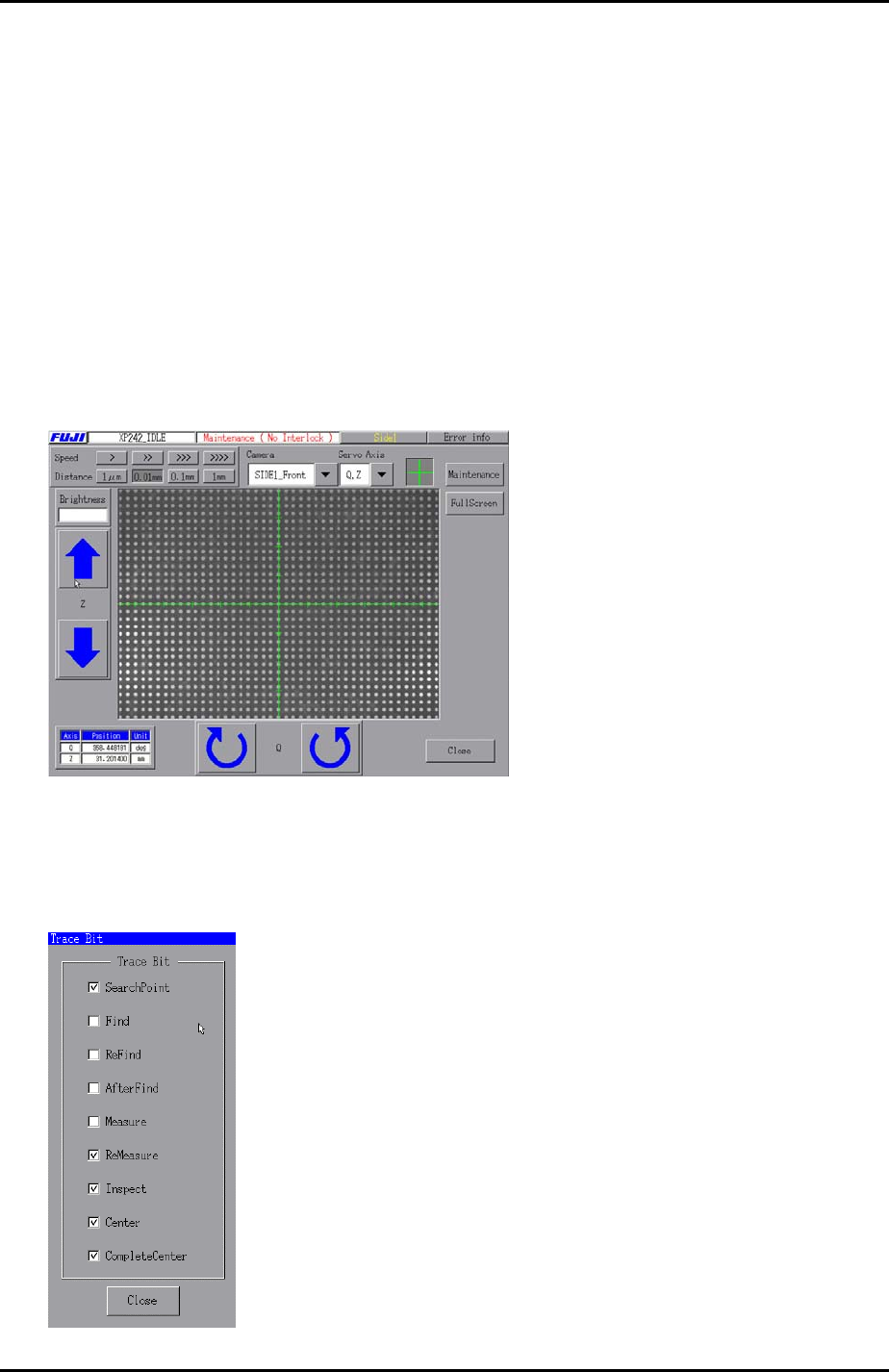
5. Set the center of the cross hairs in the center of one of the central dots on the glass
gage as illustrated below:
6. Select [Maintenance A] – [Trace Bit] and select “SearchPoint”, “ReMeasure”,
“Inspect”, “Center”, and “Complete Center”as shown below:
Fuji Machine Mfg. Co., Ltd. Okazaki.
SMT Equipment Quality Assurance Dept.
6 – 17 CS Section
FK-9F98-34 XP Type II Series Training Text for Service Engineers
Edition 2.0 XP242E – Chapter 6 Proper Data Measurements Page 18 of 30
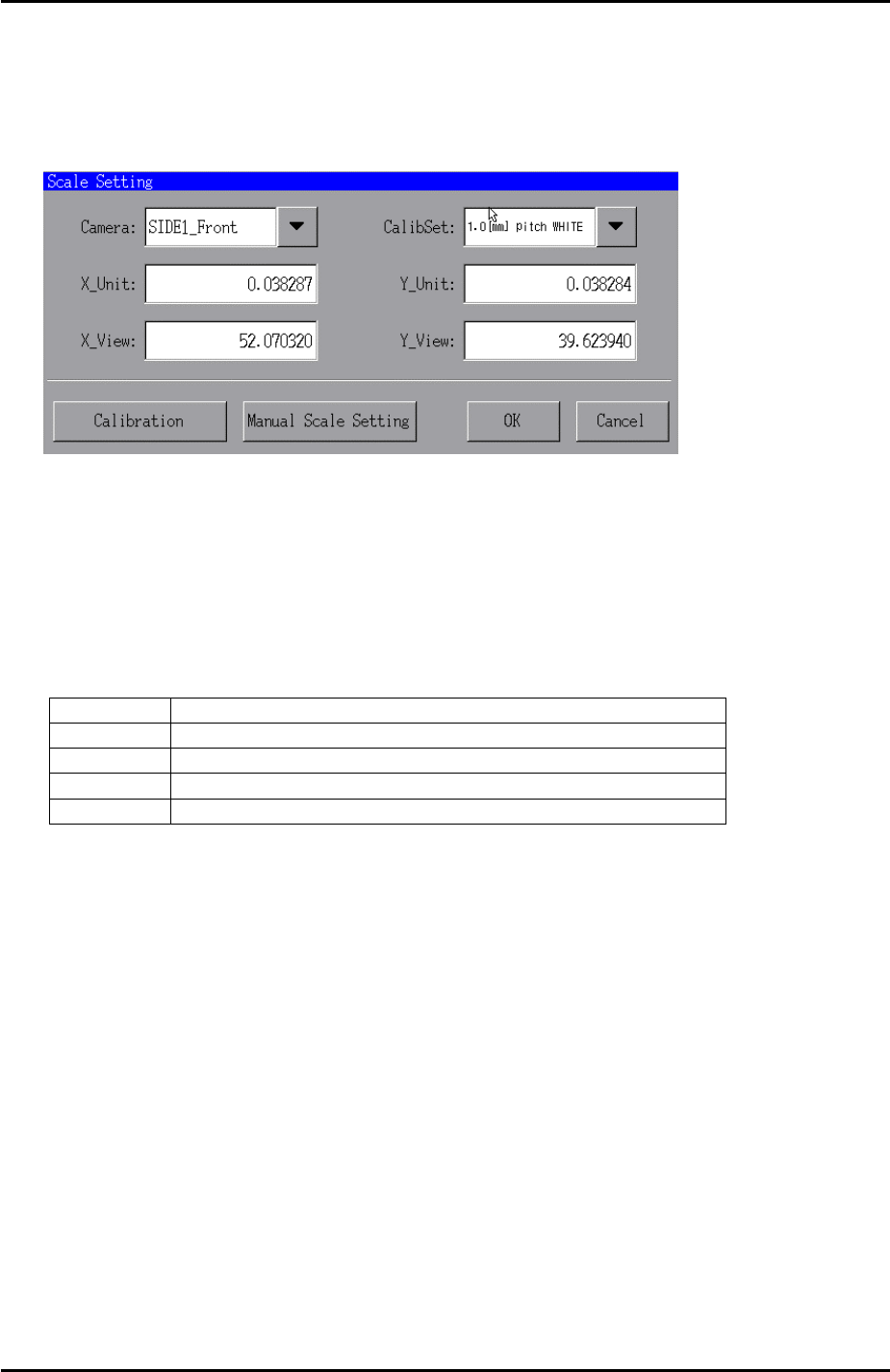
7. Select [Maintenance A] – [Scale Setting] and make sure the 200V power supply to
the servos ON.
8. Select “SIDE1_Front” from the [Camera] drop down list and “1.0 [mm] pitch WHITE”
from the [CalibSet] drop down list as shown below:
9. Press [Calibration] and answer YES to the question “Set Center?” and the
resolution measurement will proceed.
10. Answer NO to the question “Do you save calibration data to FD?”.
11. To the next question, “Save calibration data?” answer YES?
12. Confirm that the resolution results are within the tolerances shown below:
Front and Rear Parts Camera Resolution Tolerance
X_Unit 0.0375 ~ 0.039
X_View 50.98 ~ 53.04
Y_Unit 0.0375 ~ 0.039
Y_View 38.81 ~ 40.37
13. Finally press [OK] to finish.
Fuji Machine Mfg. Co., Ltd. Okazaki.
SMT Equipment Quality Assurance Dept.
6 – 18 CS Section

FK-9F98-34 XP Type II Series Training Text for Service Engineers
Edition 2.0 XP242E – Chapter 6 Proper Data Measurements Page 19 of 30
6.10 Nozzle Pickup Position
1. Equipment: Nozzle jig (Z9731DEPJ0070). Ring jig (Z9531DEPJ0020).
2. Set the ring jig in the nozzle station number 1 pocket and the nozzle jig on the
placing head.
9
8
7
6
5
4
3
1
2
3. Select [Maintenance A] – [Jog] – and carefully inch the placing head above the
nozzle station number 1 pocket.
4. Press the emergency stop button to cut the 200 volt power supply to the servos and
then manually move the X, Y and Z axes until the nozzle jig can fit smoothly into the
ring jig.
5. Select [Maintenance C] – [Proper data editor] – [Nozzle position] –
[X_NzlPosX1/Y_NzlPosY1] – [Direct Servo Input] to save the current X-axis and Y-
axis servo counts to proper data.
6. Remove the nozzle jig from the placing head.
7. Confirm that the emergency stop button is pressed so that the 200 volt power
supply to the servos is OFF, and then manually move the Z axis until the placing
head just contacts the ring jig. Record the Z-axis counter value at this position.
8. Repeat this procedure for all nine of the nozzle station pockets and calculate the
average Z-axis counter value.
9. Select [Maintenance A] – [Jog] and manually move the Z-axis to the average
counter value.
10. Use inching to raise the Z-axis a further 0.1mm, and select [Maintenance C] –
[Proper data editor] – [Nozzle position] – [Z_NzlPosZ1] – [Direct Servo Input] to
save the current Z-axis position in proper data.
11. To calculate the maximum nozzle height add 51.5mm to the “Z_NzlPosZ1” value.
12. Bring the Z-axis to the new value and select [Z_NzlPosZH] – [Direct Servo Input] to
save the maximum nozzle height in proper data.
Fuji Machine Mfg. Co., Ltd. Okazaki.
SMT Equipment Quality Assurance Dept.
6 – 19 CS Section