XP Type II 工程师培训手册 (2.0).pdf.pdf - 第21页
FK-9F98-34 XP T ype II Series T raining T ext for Service Engineers Edition 2.0 XP142E – Chapter 2 Origin settings Page 2 of 6 Fuji Machine Mfg. Co., Ltd. Okazaki 2.2 Checking the R, Q and Z Servo Parameters 1. The R, Q,…

FK-9F98-34 XP Type II Series Training Text for Service Engineers
Edition 2.0 XP142E – Chapter 2 Origin settings Page 1 of 6
Fuji Machine Mfg. Co., Ltd. Okazaki
Chapter 2 – Origin Settings
2.1 Checking the X, Y, F and G Servo Parameters
1. Equipment: digital operator (JUSP-0P02A).
2. Press the emergency stop button to cut the 200-volt power supply to the servos.
3. Connect the digital operator to the relevant servo amplifier, (“bb” displays at the screen).
4. Press [DSPL/SET] to select the channel mode (Pn000).
5. Specify the number of the channel to be checked, then press [DATA/ENTER] to display.
6. Ensure that the values match those listed in the servo amp parameter list (the most
recent list at the time of publication can be found in the supplementary section of this
manual, however always check to see if the list has been updated).
7. When you have completed checking the parameters, return to the “bb” screen.
8. If any of the servo parameter values are changed, the machine must be rebooted before
continuing with adjustments.
9. If the “multiturn” limit parameter Pn205 is changed “A.CC” will display on the amp. In this
case connect a digital operator to the amp.
10. Press the M/C emergency stop button and then release it.
11. Press [DSPL/SET] and select channel Fn000.
12. Press the up key to select channel Fn013.
13. Press [DATA/ENTER] to display [PGSET].
14. Press [DSPL/SET] and (done) displays for one second.
15. Return to Fn000 and press [DSPL/SET] to return to the initial screen, which will still
display “A.CC” until the machine is rebooted.
16. Reboot the machine and confirm that “bb” or “run’ displays on the amp.
SMT Equipment Quality Assurance Dept.
2 – 1 CS Section
FK-9F98-34 XP Type II Series Training Text for Service Engineers
Edition 2.0 XP142E – Chapter 2 Origin settings Page 2 of 6
Fuji Machine Mfg. Co., Ltd. Okazaki
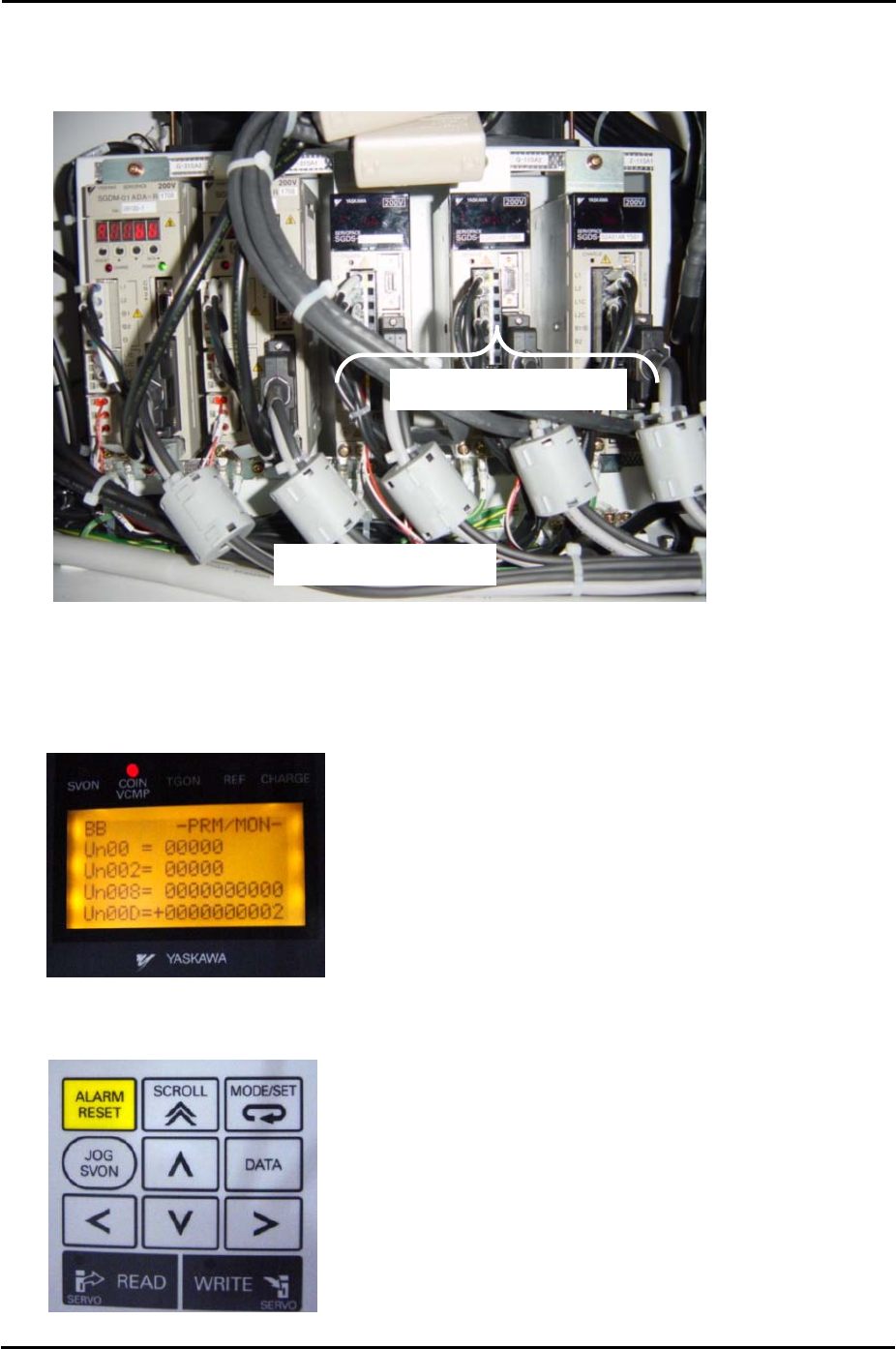
2.2 Checking the R, Q and Z Servo Parameters
1. The R, Q, and Z servo axis amplifiers in the side 2 electric box are 3∑ amplifiers.
Side 2 Electric Box
Q Z
R
3∑ Servo Amplifiers
2. To check the servo parameters connect a digital operator (JUSP-OPO5A) to the relevant
amp.
3. After connecting the digital operator to the amplifier the following screen displays:
4. Use the LEFT and RIGHT arrow keys to select the “Un” segment of the “Un00” entry in
the second line of the digital display.
SMT Equipment Quality Assurance Dept.
2 – 2 CS Section

FK-9F98-34 XP Type II Series Training Text for Service Engineers
Edition 2.0 XP142E – Chapter 2 Origin settings Page 3 of 6
Fuji Machine Mfg. Co., Ltd. Okazaki
5. Use the UP and DOWN arrow keys to set the entry to Pn000.
6. Use the LEFT and RIGHT arrow keys to select the “0” furthest to the right of the “Pn000”
entry. Check the parameter value for Pn000.
7. Use the UP arrow key to select the next entry “Pn001” and check the parameter value for
that entry.
8. Continue using the UP arrow key to check all servo parameters on the servo amp
parameter list (the most recent list at the time of publication can be found in the
supplementary section of this manual, however always check to see if the list has been
updated).
9. If it is necessary to change one of the parameter values press the [DATA] key on the
digital operator.
10. Use the arrow keys to change the value and then press [DATA] again to return.
2.3 Resetting the X, Y, F and G Servo Amplifiers
1. The amplifiers must be reset in the following cases:
• An amplifier is replaced or removed.
• A motor is replaced or removed.
• An encoder cable is replaced or removed.
• An axis tension belt is replaced or removed.
• An axis pulley is replaced or removed.
2. Press the emergency stop button and set the relevant axis at its origin position (X and Y
are set against their minus mechanical stopper, for details of the origin position for F and
G refer to “2.5 Setting the Axis Origins”.
3. Connect a digital operator to the target amplifier (“bb” or error code displays).
4. Press [DSPL/SET] to select the “Fn000” channel mode.
5. Press the [▲] arrow key to select channel “Fn008”.
6. Press [DATA/ENTER] to display “PGCL1”.
7. Press the [▲] arrow key to set it to “PGCL5”.
8. Press [DSPL/SET] and “done” displays.
9. Press [DATA/ENTER] to return to channel “Fn008”.
10. Press the [▼] arrow key to return to “Fn000”.
11. Press [DSPL/SET] to return to the original display.
12. Remove the digital operator from the target amplifier and restart the machine.
SMT Equipment Quality Assurance Dept.
2 – 3 CS Section