XP Type II 工程师培训手册 (2.0).pdf.pdf - 第116页
FK-9F98-34 XP T ype II Series T raining T ext for Service Engineers Edition 2.0 XP242E – Chapter 2 Origin Settings Page 3 of 4 2.4 Setting the Axis Origins 1. Press the emergency stop button and set each axis against its…
FK-9F98-34 XP Type II Series Training Text for Service Engineers
Edition 2.0 XP242E – Chapter 2 Origin Settings Page 2 of 4
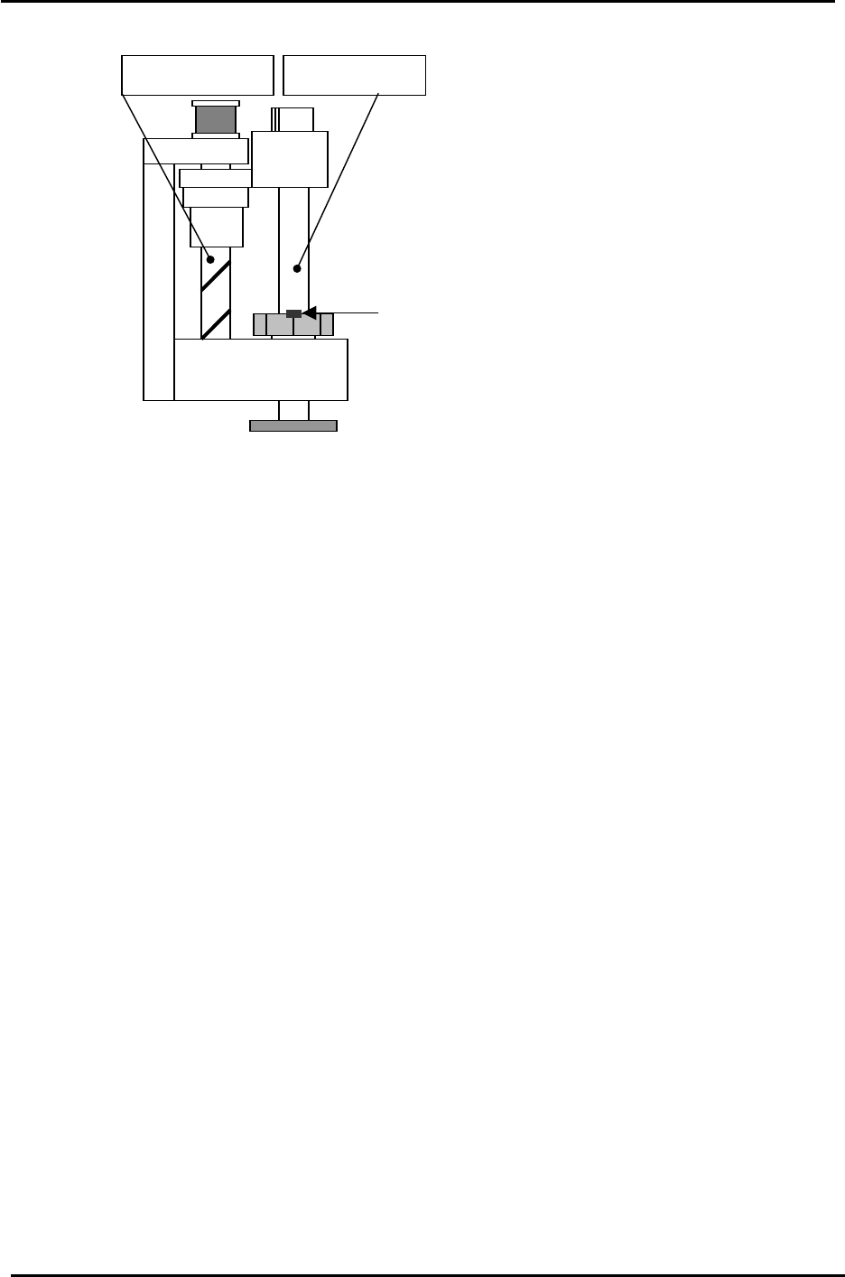
The spline shaft bearing retaine
r
bolt faces out towards the machine
front at side 1.
Spline shaft Z-axis ball screw
3. Connect a digital operator to the target amplifier (“bb” or error code displays).
4. Press [DSPL/SET] to select the “Fn000” channel mode.
5. Press the [↑] arrow key to select channel “Fn008”.
6. Press [DATA/ENTER] to display “PGCL1”.
7. Press the [▲] arrow key to set it to “PGCL5”.
8. Press [DSPL/SET] and “done” displays.
9. Press [DATA/ENTER] to return to channel “Fn008”.
10. Press the [▼] arrow key to return to “Fn000”.
11. Press [DSPL/SET] to return to the original display.
12. Remove the digital operator from the target amplifier and restart the machine.
13. After setting the amplifier origin set the axis origin by following the procedure described in
“2.4 Setting the Axis Origins”.
Fuji Machine Mfg. Co., Ltd. Okazaki.
SMT Equipment Quality Assurance Dept.
2 – 2 CS Section
FK-9F98-34 XP Type II Series Training Text for Service Engineers
Edition 2.0 XP242E – Chapter 2 Origin Settings Page 3 of 4
2.4 Setting the Axis Origins
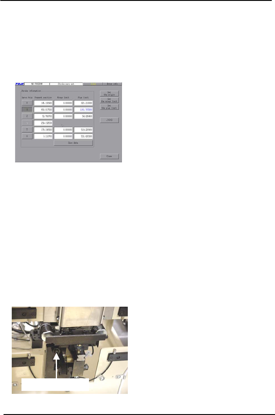
1. Press the emergency stop button and set each axis against its minus mechanical
stopper. For the T or U axes refer to the “XP242E T and U Axes Brake Bypass
Procedure” in the supplementary section of this manual. Select [Maintenance C] –
[Stroke Zero Set] and the following screen displays:
2. Select the axis you are setting and then press [Set the origin].
3. When the origin adjustments are complete, select [Maintenance C] – [Proper Data Editor]
– [Servo Limit] and check that the “Minus Limit” proper data item for all of the axes is 0. If
not set to 0.
2.5 Setting the Plus Software Limits
1. Set each axis to its plus mechanical stopper. Refer to the mechanical stopper location
diagrams in the supplementary section of this manual.
2. In the case of the U axis remove the tray catch stopper and bypass the brake before
pushing the shuttle to its plus limit (MTU side).
Tray Catch Stopper
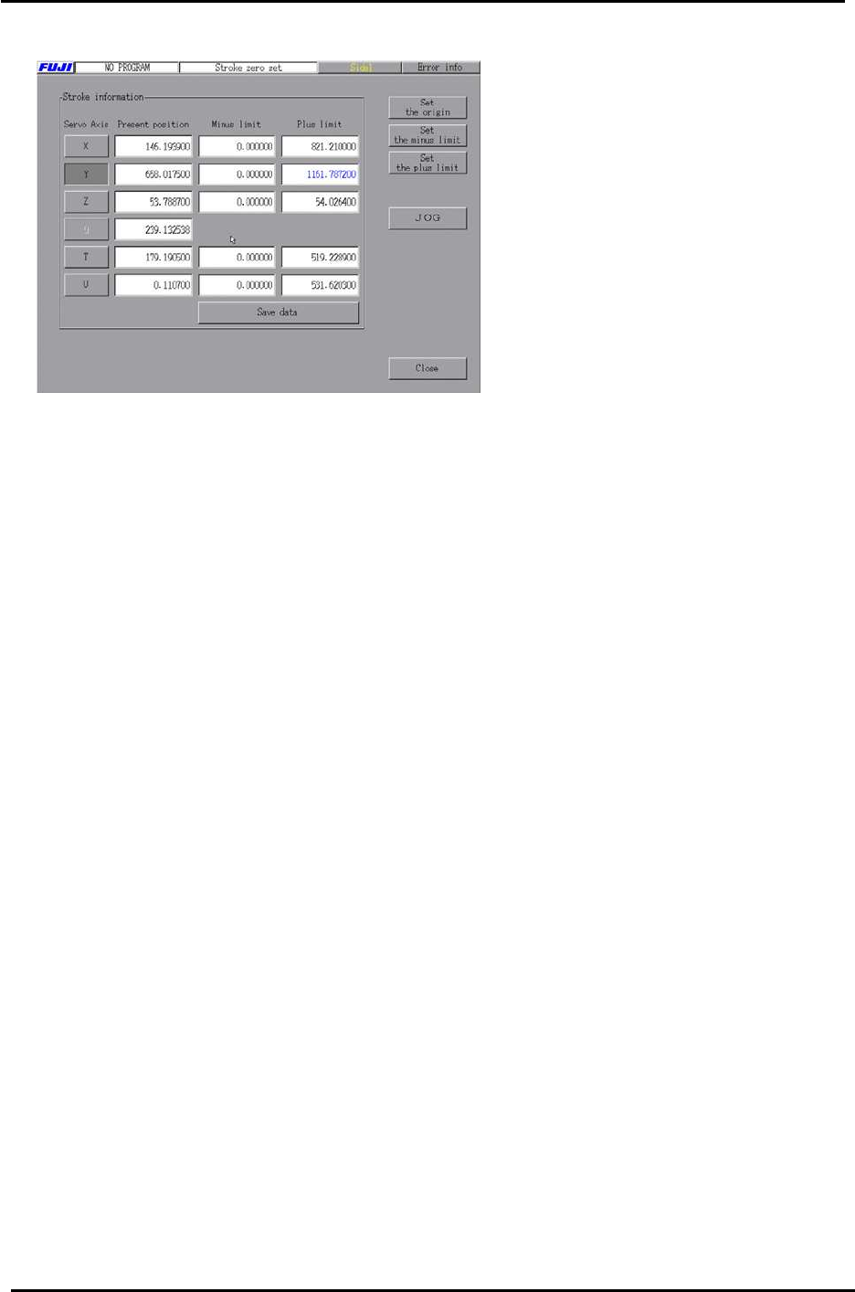
3. Select [Maintenance C] – [Stroke Zero Set].
Fuji Machine Mfg. Co., Ltd. Okazaki.
SMT Equipment Quality Assurance Dept.
2 – 3 CS Section
FK-9F98-34 XP Type II Series Training Text for Service Engineers
Edition 2.0 XP242E – Chapter 2 Origin Settings Page 4 of 4
4. Select the axis you are setting and then press [Set the plus limit].
Fuji Machine Mfg. Co., Ltd. Okazaki.
SMT Equipment Quality Assurance Dept.
2 – 4 CS Section