XP Type II 工程师培训手册 (2.0).pdf.pdf - 第215页
FK-9F98-34 XP T ype II Series T raining T ext for Service Engineers Edition 2.0 XP242E – Chapter 9 Options Page 3 of 12 Only holes in this line have a vacuum backup air supply 3. An air valve can be used to switch the va…
FK-9F98-34 XP Type II Series Training Text for Service Engineers
Edition 2.0 XP242E – Chapter 9 Options Page 2 of 12
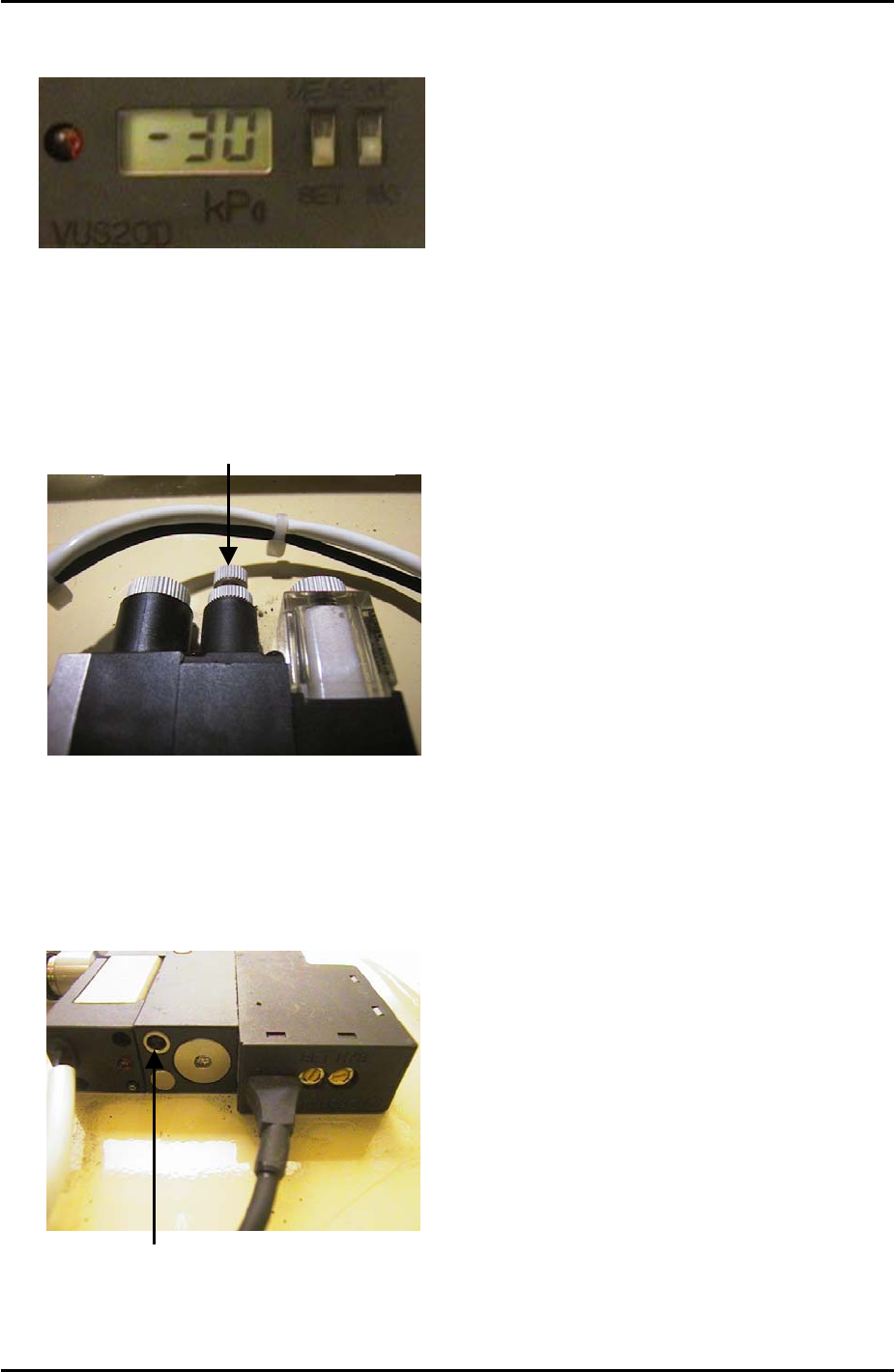
2. Set the Pressure Trimmer (SET) to –30cmHg.
Speed Controller Adjustment
1. Turn the air blow volume controller 3 turns from fully closed and lock.
Air Blow Volume Controller
2. Use a minus screw driver to turn the air blow release timer fully closed clockwise. From
this position turn the timer 7 turns counter clockwise. Turning the timer clockwise will
increase the air blow release time. Turning it counter clockwise will decrease the air blow
release time.
Air Blow Release Timer
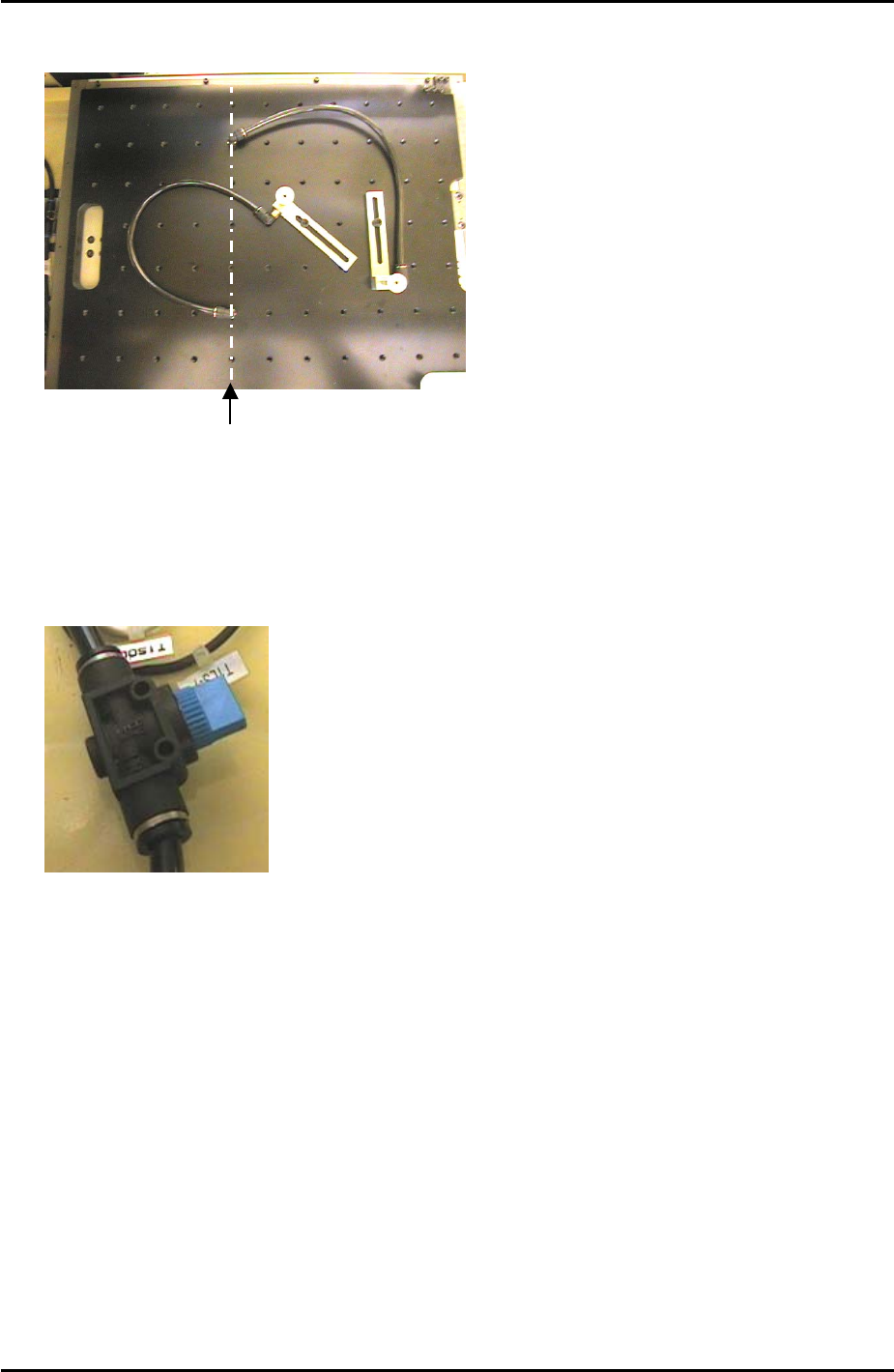
3. When setting up the vacuum back up pins on the back up plate the air terminals should
be screwed into the correct holes. The vacuum air supply is only available from the Y-
direction line 5 holes from the back up plate left hand side.
Fuji Machine Mfg. Co., Ltd. Okazaki
SMT Equipment Quality Assurance Dept.
9 – 2 CS Section
FK-9F98-34 XP Type II Series Training Text for Service Engineers
Edition 2.0 XP242E – Chapter 9 Options Page 3 of 12
Only holes in this
line have a vacuum
backup air supply
3. An air valve can be used to switch the vacuum backup air supply ON and OFF.
Fuji Machine Mfg. Co., Ltd. Okazaki
SMT Equipment Quality Assurance Dept.
9 – 3 CS Section
FK-9F98-34 XP Type II Series Training Text for Service Engineers
Edition 2.0 XP242E – Chapter 9 Options Page 4 of 12
9.2 Coplanarity Camera Adjustment
Equipment
1. Coplanarity Jig (Z9631DEPJ3410).
Camera Setting
1. Set the coplanarity camera aperture to 8 and lock the hollow bolt with Loctite 425.
Proper Data Setting
1. Select [Maintenance C] – [Proper Data Editor] – [MACHINE_TYPE] – and set
[Coplanarity] to 1.
2. Select [OTHERS] and set the following proper data items:
Proper Data Item Setting
X_CoplanarityPosX 625
Y_CoplanarityPosY Same as [PrismBack] position
Z_CoplanarityPosZ 41
CoplaCamShutterSpeed 3500
Vision Processing Position
1. Make sure that there is a 2.5mm diameter nozzle in the nozzle station and in the
nozzle editor.
2. Select [Maintenance C] – [Custom Maintenance] and select the [Coplanarity] camera
from the camera drop down list.
3. Select [Maintenance] – [Focus adjustment] – and press and hold down the [START]
button until the “Manually Pick-Up the focus jig” message appears.
4. Press [OK] – [Focus adjustment] and press and hold down the [START] button until
the “Move” message displays. The nozzle is now at the vision processing position.
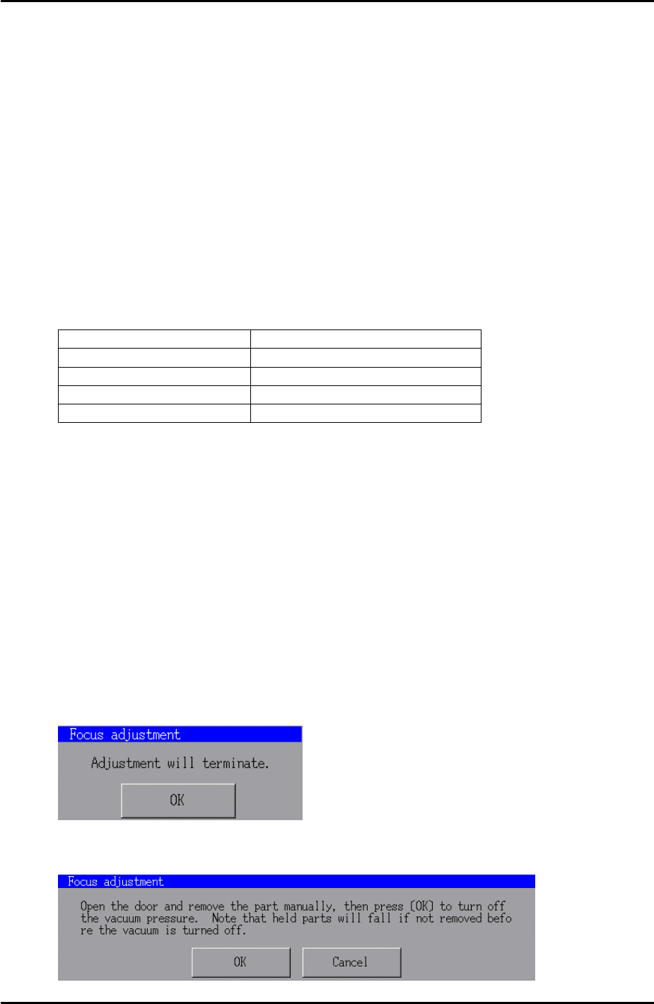
5. Press [OK] – [Complete] and the following message displays:
6. Press [OK] – [Close] and the following message displays:
Fuji Machine Mfg. Co., Ltd. Okazaki
SMT Equipment Quality Assurance Dept.
9 – 4 CS Section