XP Type II 工程师培训手册 (2.0).pdf.pdf - 第71页
FK-9F98-34 XP T ype II Series T raining T ext for Service Engineers Edition 2.0 XP142E – Chapter 6 Proper Dat a Measurement s Page 12 of 30 6. Select the cross hairs and then adju st the posi tion of the resolution measu…
FK-9F98-34 XP Type II Series Training Text for Service Engineers
Edition 2.0 XP142E – Chapter 6 Proper Data Measurements Page 11 of 30
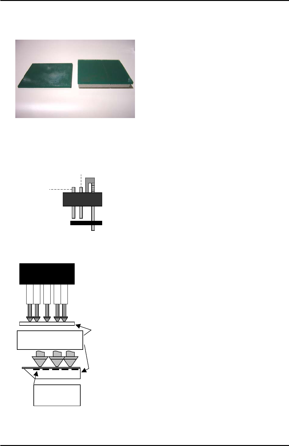
6.7 Parts Camera Resolution Measurement (Low Parts)
1. Equipment: resolution measurement jigs (Z3502DEAJ0020).
Low Parts
Standard
2. Insert 1.8mm nozzles in all of the nozzle pistons.
3. In [Maintenance Mode] select [Maintenance] – [I/O Check] – [Y016 VacuumPump] – [ON]
and lower all the vacuum pins on the revolver.
Air blow pin
Vacuum pin
4. Put the low parts resolution measurement jig on the revolver with the printed surface
uppermost:
Resolution measurement
glass gauge.
Printed surface
uppermost
5. Select the [SIDE1] camera and inch the Y-axis to the [PrismFront] position.
Fuji Machine Mfg. Co., Ltd. Okazaki
SMT Equipment Quality Assurance Dept.
6 – 11 CS Section
FK-9F98-34 XP Type II Series Training Text for Service Engineers
Edition 2.0 XP142E – Chapter 6 Proper Data Measurements Page 12 of 30
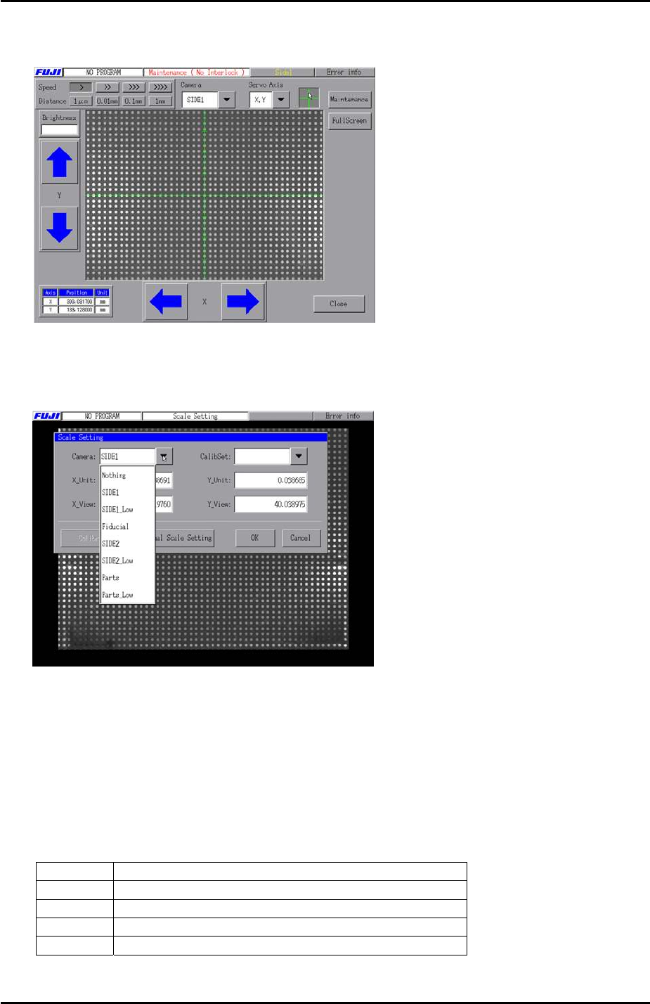
6. Select the cross hairs and then adjust the position of the resolution measurement jig until
the center dot is in the center of the camera cross hairs.
7. Press [Close] to exit Maintenance Mode and then select [Maintenance A] – [Scale
Setting] and choose [SIDE1_Low] from the “Camera” drop down list. Select “1.0 [mm]
pitch WHITE” from the [CalibSet] drop down list.
8. Make sure that the 200V are ON then press [Calibration] and answer [YES] to the
question “Set Center?” The resolution measurement will proceed.
9. Answer NO to the question “Do you save calibration data to FD?”
10. To the next question “Save calibration data?” answer YES.
11. Confirm that the resolution results are within the tolerances described below:
Parts camera resolution tolerance (Standard)
X_Unit
0.03607511 ~ 0.0409173
X_View
49.10798 ~ 55.6995
Y_Unit
0.03607511 ~ 0.0409173
Y_View
37.27699 ~ 42.2805
12. Press [OK] to return to the [Maintenance A] screen and repeat steps 5 to 11 for side 2.
Fuji Machine Mfg. Co., Ltd. Okazaki
SMT Equipment Quality Assurance Dept.
6 – 12 CS Section
FK-9F98-34 XP Type II Series Training Text for Service Engineers
Edition 2.0 XP142E – Chapter 6 Proper Data Measurements Page 13 of 30
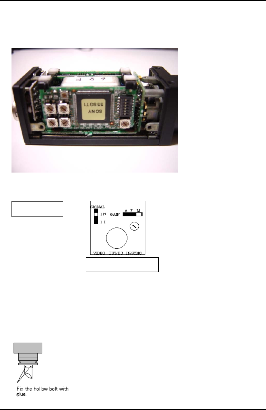
6.8 Mark Camera Setting
1. On a new camera remove the cover and check that the internal settings are as shown in
the following photo:
2. Set the mark camera settings as outlined in the following table and diagram:
Top view of the camera
Signal 1N
Gain M
3. If attaching the mark camera unit to the mark camera installation bracket use 0.5N.m
torque.
4. Ensure that the join where the camera lens unit and camera are connected is reinforced
with adhesive.
5. Ensure that adhesive (Loctite 425) is applied to the hollow bolts that hold the half mirror
in place. Do not over apply adhesive.
The orientation of the half-mirror is
not critical to the mark camera
operation; therefore any orientation
is acceptable.
Fuji Machine Mfg. Co., Ltd. Okazaki
SMT Equipment Quality Assurance Dept.
6 – 13 CS Section