XP Type II 工程师培训手册 (2.0).pdf.pdf - 第229页
T T a a n n d d U U A A x x i i s s B B r r a a k k e e B B y y p p a a s s s s
FK-9F98-34 XP Type II Series Training Text for Service Engineers
Edition 2.0 Supplementary Information
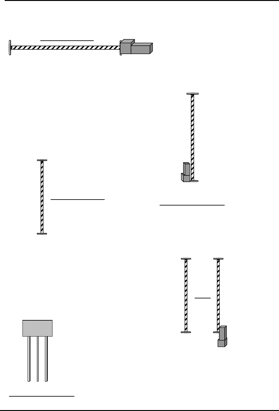
XP242E Mechanical Stopper Locations
Front View of X axis
- Mechanical
Stopper
+ Mechanical
Stopper
+ Mechanical Stopper
+ Mechanical Stopper
- Mechanical Stopper
Front View of Z Axis
Overhead View of Y axis
- Mechanical Stopper
+ Mechanical Stopper
T axis
- Mechanical Stopper
- Mechanical Stopper
+ Mechanical Stopper
MTU
Overhead View of U axis
Fuji Machine Mfg. Co., Ltd. Okazaki
SMT Equipment Quality Assurance Dept.
CS Section

T
T
a
a
n
n
d
d
U
U
A
A
x
x
i
i
s
s
B
B
r
r
a
a
k
k
e
e
B
B
y
y
p
p
a
a
s
s
s
s
FK-9F98-34 XP Type II Series Training Text for Service Engineers
Edition 2.0 Supplementary Information
XP242E T and U Axes Brake Bypass Procedure
A brake is used on the T and U axes to prevent these axes moving even when the servo
power is OFF. However when resetting the T or U axis servo amplifiers (2.3 Resetting
the Servo Amplifiers), or setting the T or U axis origins (2.4 Setting the Origins) it is
necessary to bypass the brake. The following describes the procedure for bypassing the
brake.
1. Make sure that the machine power is ON.
2. Press the emergency stop button to cut the 200V power supply to the servos.
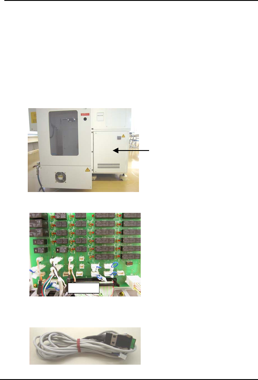
3. Locate servo box 2 at the rear of the machine next to the MTU:
Servo Box 2
4. Open the door and locate the relay PCB (M1PCB2) on the other side of the door:
M1PCB
5. Prepare a brake cancel switch such as that shown below (if this is not available a
small minus driver can be used instead).
Fuji Machine Mfg. Co., Ltd. Okazaki
SMT Equipment Quality Assurance Dept.
CS Section