XP Type II 工程师培训手册 (2.0).pdf.pdf - 第48页
FK-9F98-34 XP T ype II Series T raining T ext for Service Engineers Edition 2.0 XP142E – Chapter 5 Peripheral Adjustm ents Page 4 of 14 5.3 T ape Leaf Sensors Initial Setting 1. Fix the attachment to the fiber sensor usi…

FK-9F98-34 XP Type II Series Training Text for Service Engineers
Edition 2.0 XP142E – Chapter 5 Peripheral Adjustments Page 3 of 14
X Direction Static Accuracy
1. Clamp the reference MFU used in previous steps to side 1.
2. Mount the device jig in slot No.2 and set the dial gage tip against the jig in the X direction.
Please refer to the illustration below:
X-direction
Tolerance: ±0.035mm
3. Set the dial to 0 and then jog the head in the Y direction to slide the dial gage tip away
from the jig.
4. Record the current X-axis servo counter value and then unclamp the MFU.
5. Clamp the second MFU (or any additional MFUs) and mount the device jig in slot No.2
and turn the servo ON.
6. Ensure the X axis counter value is the same as that recorded in step 4 and then jog the
head in the Y direction until the dial gage tip contacts the jig.
7. Check the difference between the reference MFU and the second MFU (or any additional
MFUs) in the X-direction. Tolerance is +/- 0.035mm.
Fuji Machine Mfg. Co., Ltd. Okazaki
SMT Equipment Quality Assurance Dept.
5 – 3 CS Section
FK-9F98-34 XP Type II Series Training Text for Service Engineers
Edition 2.0 XP142E – Chapter 5 Peripheral Adjustments Page 4 of 14
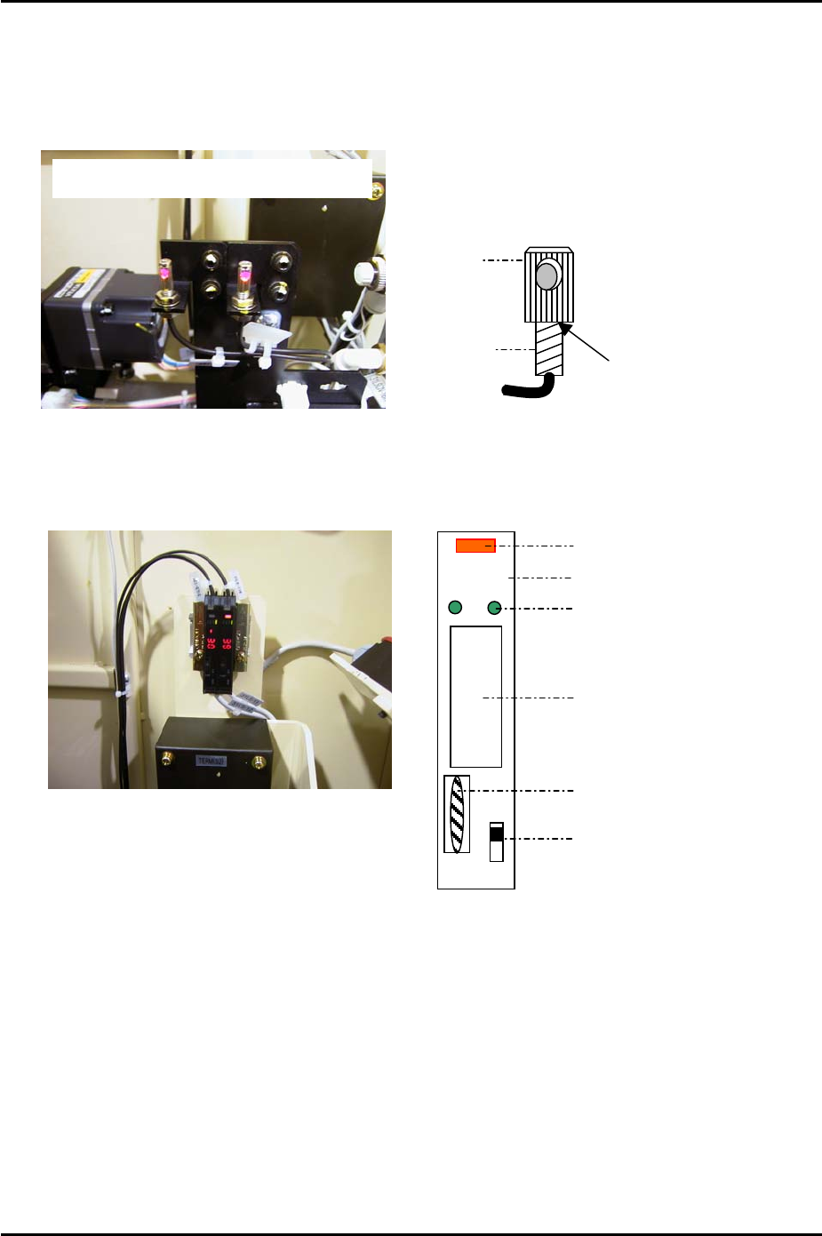
5.3 Tape Leaf Sensors
Initial Setting
1. Fix the attachment to the fiber sensor using Loctite 222 adhesive.
Double detection type tape leaf sensors
A
pply Loctite 222 here
Fiber sensor
A
ttachment
Amplifier Frequency Setting
DOLO
RUN
SET
TMR
ADJ
Digital Display
Operation Light
Mode Lights
Mode Display
Dial Switch
L-ON/D-ON Changeover Switch
1. Set the L-ON/D-ON changeover switch to L_ON.
2. Press the dial switch once (the RUN light in the Mode Display flashes and “AA” is
displayed on the digital display).
3. Turn the dial switch until SET flashes on the “Mode Display”.
4. Press and hold the dial switch for 3 seconds (SET stops flashing and the Mode Lights
come ON).
5. Turn the dial switch until “– –“ is displayed on the digital display.
6. Press and hold the dial switch for 8 seconds.
Fuji Machine Mfg. Co., Ltd. Okazaki
SMT Equipment Quality Assurance Dept.
5 – 4 CS Section
FK-9F98-34 XP Type II Series Training Text for Service Engineers
Edition 2.0 XP142E – Chapter 5 Peripheral Adjustments Page 5 of 14
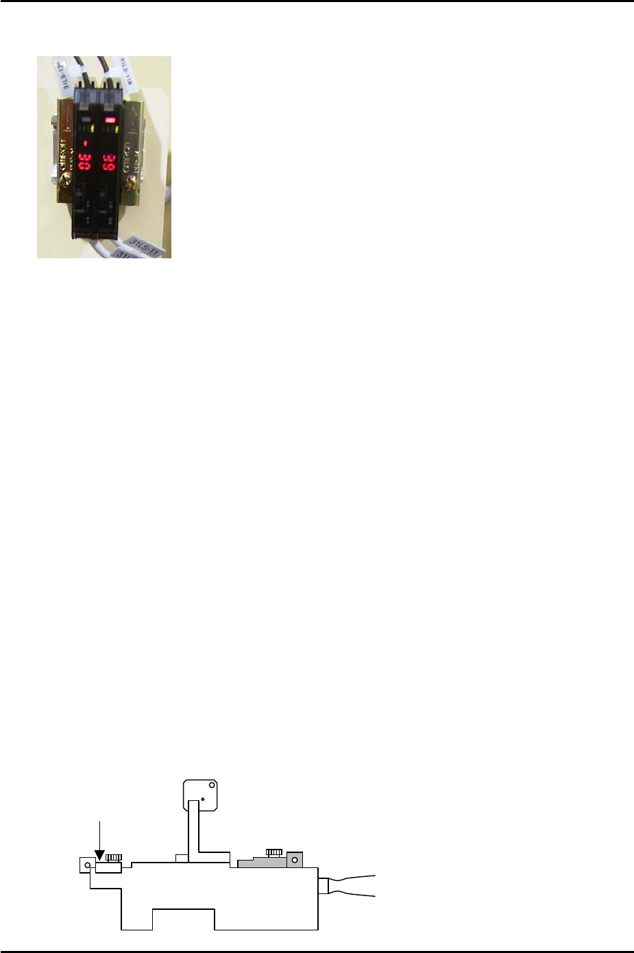
7. Turn the dial to select F1 or F2 depending on which of the two amplifiers are being
adjusted (refer to the photo of the amplifiers below).
Side 1
F1
F2
8. Press the dial switch once so that SET in the Mode Display flashes.
9. Turn the dial until RUN in the mode display flashes.
10. Press the dial switch once (RUN stops flashing and a number 1~100 displays in the
digital display).
11. Repeat the procedure for the other amp.
HP Mode and Sensor Position Setting
1. Press the dial switch once (the RUN light in the Mode Display flashes and “AA” is
displayed on the digital display).
2. Turn the dial switch until SET flashes on the “Mode Display”.
3. Press and hold the dial switch for 3 seconds (SET stops flashing and the Mode Lights
come ON).
4. Turn the dial switch until “HP” is displayed on the digital display.
5. Press the dial switch once (SET in the mode display flashes).
6. Press the dial switch once so that “2P” flashes on the digital display.
7. Turn the dial until a number 1~100 displays on the digital display.
8. Clamp the MFU and set two sensor adjustment jigs (Z9731ADEPJ8070) in slots D47 and
D49.
Front Attachment
Z9631ADEPJ8070
Fuji Machine Mfg. Co., Ltd. Okazaki
SMT Equipment Quality Assurance Dept.
5 – 5 CS Section