XP Type II 工程师培训手册 (2.0).pdf.pdf - 第40页
FK-9F98-34 XP T ype II Series T raining T ext for Service Engineers Edition 2.0 XP142E – Chapter 4 Loader Adjustment Page 9 of 12 7. Adjust the position of the main stopper as is shown in the following dia gram: Note: Se…
FK-9F98-34 XP Type II Series Training Text for Service Engineers
Edition 2.0 XP142E – Chapter 4 Loader Adjustment Page 8 of 12
Table
Front of the
machine
Upper limit
sensor
Lower limit
senso
r
Adjust the
fla
g
Checking the Lifter Speed
1. Select [Manual Operation] – [Conveyor Operation] – [Main Lifter Up/Down] to raise and
lower the main lifter. The travel time should be in the following range:
Moving UP 400 – 600 ms
Moving DOWN 700 – 900 ms
Note: If the travel time is not in the range, re-adjust the main lifter speed controllers.
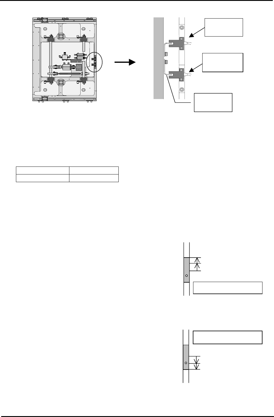
4.7 Main Stopper
Measuring jig: Plate jig (AJPJ-0060)
Main stopper down
Sensor OFF
Sensor ON: raise 1mm
Fix the Sensor
1. Select [Maintenance A] – [I/O Check] – and turn [Y02A
MainStationStp] OFF to lower the main stopper.
2. Lower the lower limit sensor [I/O X01F
MainStStpOffChk] until it turns OFF.
3. Raise the lower limit sensor, and lock the sensor 1mm
above the point it first turns ON.
Main stopper up
Sensor OFF
Sensor ON: Lower 1mm
Fix the sensor
4. 4.Select [Maintenance A] – [I/O Check], and turn ON
I/O [Y02A MainStationStop] to raise the main stopper.
5. Raise the upper limit sensor [I/O X01E
MainStStpOnChk] until it turns OFF.
6. Lower the upper limit sensor, and fasten the sensor
1mm below the point the sensor first comes ON.
Fuji Machine Mfg. Co., Ltd. Okazaki.
SMT Equipment Quality Assurance Dept.
4 – 8 CS Section
FK-9F98-34 XP Type II Series Training Text for Service Engineers
Edition 2.0 XP142E – Chapter 4 Loader Adjustment Page 9 of 12
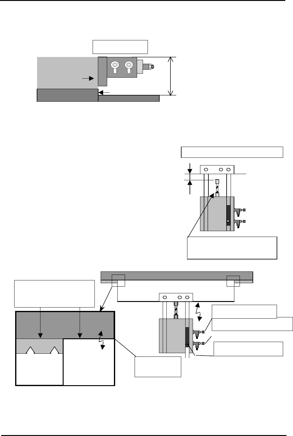
7. Adjust the position of the main stopper as is shown in the following diagram:
Note: Set the board stopper at a right angle to the fixed rail.
Main Stopper
45 ~ 47mm
Plate jig
(AJPJ-0060)
Place the stopper leading edge at the
same position as the board clamper edge.
4.8 In Lifter
1. Select [Maintenance A] – [I/O Check], and turn I/O
[Y02D InStLftUpChk] ON to raise the in-lifter.
2. Adjust the cylinder stopper bolt so that the clearance
between the in-lifter air cylinder stopper and
underside of the lifter plate becomes 1.0mm.
3. Turn I/O [Y02D InStLifterUp] OFF to lower the in-
lifter. The top of the lifter plate should now be flush
with the conveyor belt top surface. If not adjust the tilt
of the lifter plate.
To adjust the clearance, adjust
the cylinder stopper bolt
Conveyor belt
top surface
Upward limit sensor
Speed controller (DOWN)
Speed controller (UP)
Backup
Plate
Lifter Plate
Conveyor Belt
A
lign the height of the plate
top surface and belt top
surface.
A
d
j
ust the clearance to 1.0mm
4. When step 3 is complete turn I/O [Y02D InStLifterUp] ON to raise the in-lifter.
5. ow repeat the procedure in step 2, but this time set the clearance to 1.5mm.
N
Fuji Machine Mfg. Co., Ltd. Okazaki.
SMT Equipment Quality Assurance Dept.
4 – 9 CS Section
FK-9F98-34 XP Type II Series Training Text for Service Engineers
Edition 2.0 XP142E – Chapter 4 Loader Adjustment Page 10 of 12
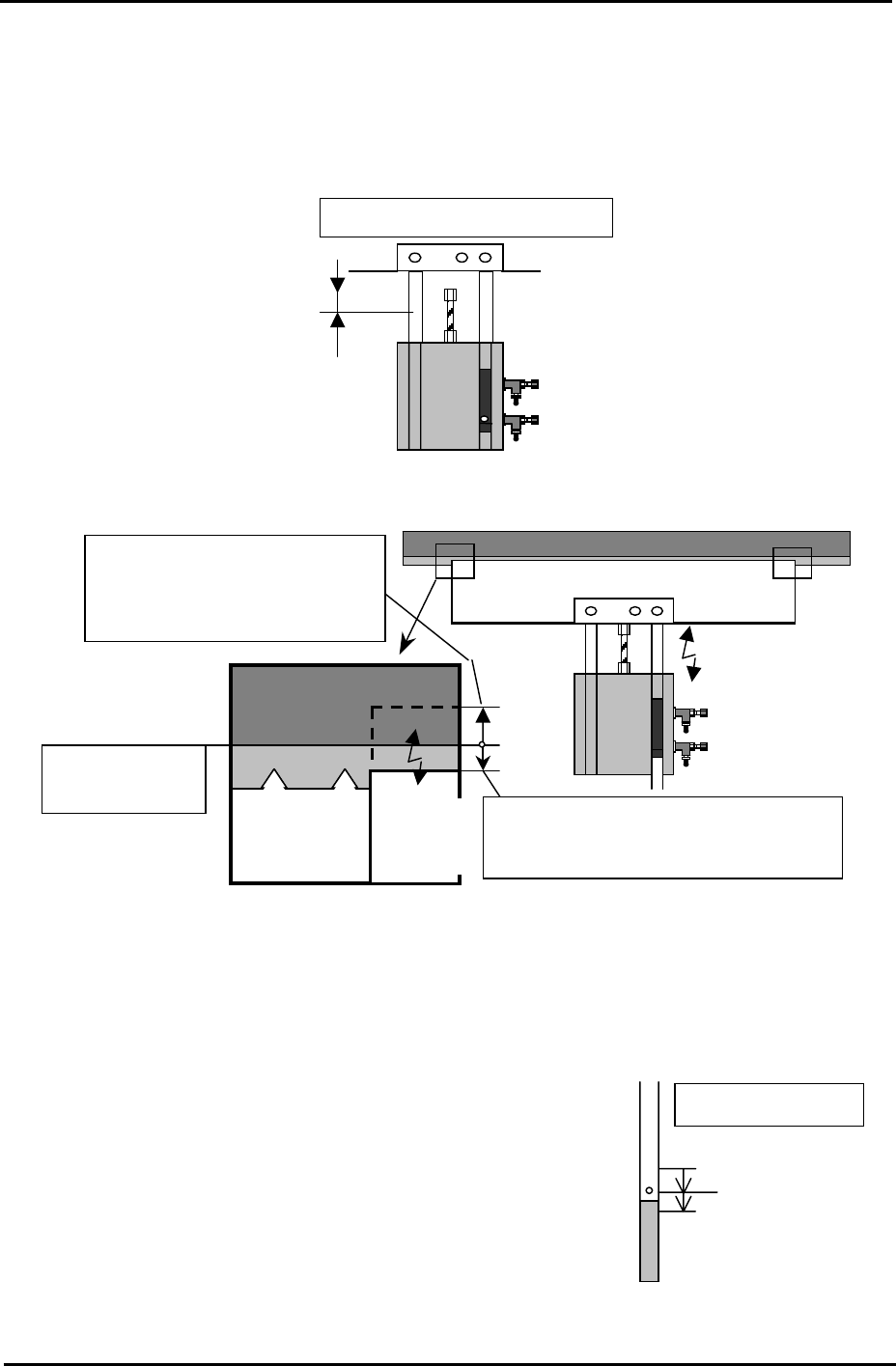
Turn I/O [Y02D InStLifterUp] OFF to lower the in-lifter. Ensure that the lifter plate top
surface is approxomately 0.5mm below
6.
the conveyor belt top surface. Use a ruler to
check. Confirm both the height and tilt.
7.
able-
side up/down speed is balanced. If not, adjust using the cylinder speed controllers.
ir Cylinder Upper Limit Sensor
1. arry
r approximately 1mm below the point that it
first comes ON.
A
djust the clearance to 1.5mm.
Top surface of
the conveyor belt
Ensure that when the plate is lowered, the
plate top surface is approximately 0.5mm
below the conve
y
or belt to
p
surface.
When the plate is raised, the plate
top surface should be raised
approx. 1mm from the conveyor
belt to
p
surface.
Lifter
Plate
Lifter Plate
Conveyor Belt
After adjustment is complete, place a board on the in-conveyor and raise the in-lifter.
Check that the board is not jolted up. And also ensure that the reference side/mov
A
Fix the sensor
ON: Lower 1mm
Sensor OFF
In-lifter (UP)
Sensor
Turn I/O [Y02D InStLifterUp] ON and raise the in-lifter. C
out the upper limit sensor adjustment. Select I/O [X028
InStLftUpChk] and slowly raise the sensor from the lower
position until the sensor turns ON and keep raising until it
goes OFF. Then, lower the sensor until it comes ON and
fasten the senso
Fuji Machine Mfg. Co., Ltd. Okazaki.
SMT Equipment Quality Assurance Dept.
4 – 10 CS Section