XP Type II 工程师培训手册 (2.0).pdf.pdf - 第149页
FK-9F98-34 XP T ype II Series T raining T ext for Service Engineers Edition 2.0 XP242E – Chapter 5 Peripheral Adjustm ents Page 1 1 of 16 5.6 Nozzle/Parts Vacuum Pressure Jig: Nozzle jig (Z9531DEPJ0070) Measuring equipme…
FK-9F98-34 XP Type II Series Training Text for Service Engineers
Edition 2.0 XP242E – Chapter 5 Peripheral Adjustments Page 10 of 16
Lubrication
1. Lubricate the sliding parts of the link arm (cutter) and LM rail.
5.5 Waste Tape Duct Height Adjustment
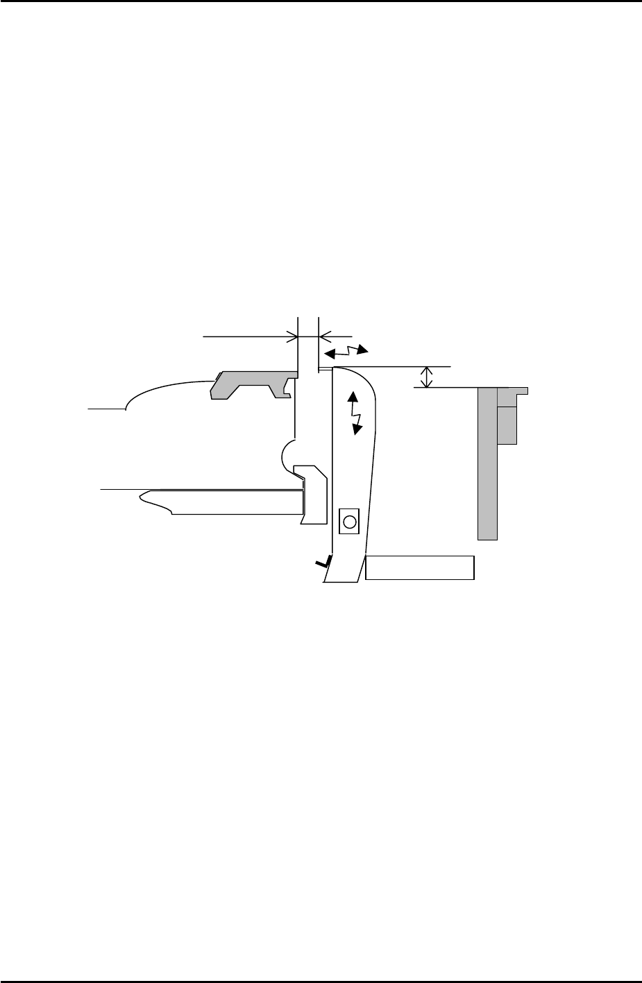
1. Attach the waste tape duct and temporarily tighten it.
2. Load a feeder on the device table and set the Y direction clearance between the feeder
and the waste tape duct to 12.5mm. Please see the diagram below:
Waste tape duct
Feeder
Conveyor
13mm
Approx. 12.5mm
3. Set the height of the waste tape duct so that it is 13mm higher than the top surface of the
conveyor. There should be sufficient clearance for the waste tape to feed down the duct
into the waste tape box without getting stuck.
4. To confirm that the waste tape duct is aligned correctly, check that the clearance and
height are the same at slot numbers 1 and 40.
Fuji Machine Mfg. Co., Ltd. Okazaki.
SMT Equipment Quality Assurance Dept.
5 – 10 CS Section
FK-9F98-34 XP Type II Series Training Text for Service Engineers
Edition 2.0 XP242E – Chapter 5 Peripheral Adjustments Page 11 of 16
5.6 Nozzle/Parts Vacuum Pressure
Jig: Nozzle jig (Z9531DEPJ0070)
Measuring equipment: Manometer, (PG-100-02VH).
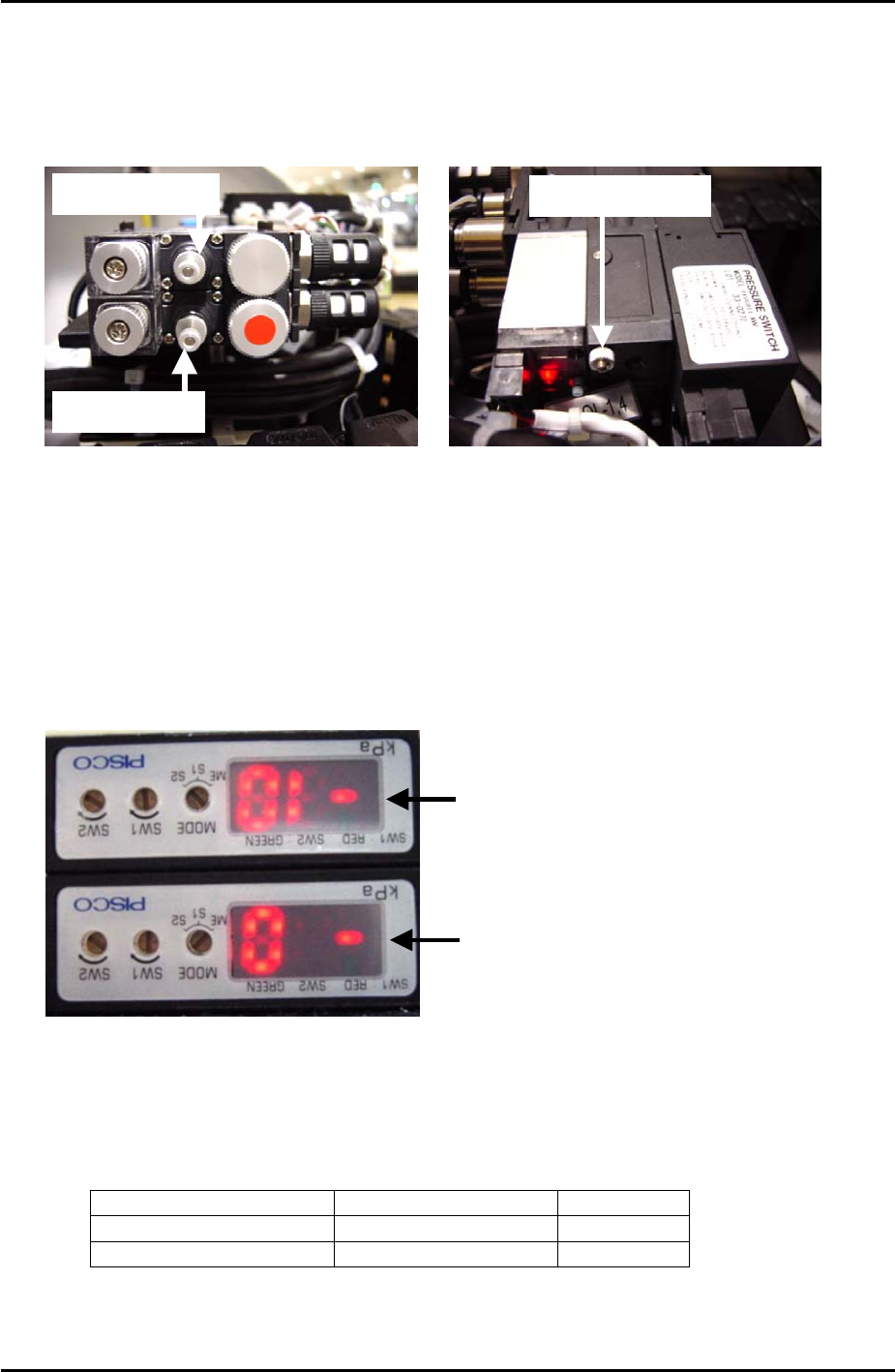
Nozzle air blow
Parts air blow
Blow time throttle
1. Refer to the picture above and turn the nozzle air blow speed controller fully open and
lock.
2. Enter I/O Y021 NozzleUnhold and adjust the blow time throttle so that the air blow is ON
for 2 seconds and then cuts out. Once the blow time is adjusted correctly, lock the
throttle.
Vacuum Sensor Setting
Nozzle Vacuum Sensor
Parts Vacuum Sensor
1. Switch the [MODE] of both vacuum sensors to S1.
2. Adjust the “SW1” volume dial on the side of the sensor until the sensor displays the
following values:
Sensor Position Value
Nozzle Vacuum Sensor Top Sensor -20
Parts Vacuum Sensor Bottom Sensor -1
3. Once the values have been set switch both vacuum sensors from S1 to ME.
Fuji Machine Mfg. Co., Ltd. Okazaki.
SMT Equipment Quality Assurance Dept.
5 – 11 CS Section
FK-9F98-34 XP Type II Series Training Text for Service Engineers
Edition 2.0 XP242E – Chapter 5 Peripheral Adjustments Page 12 of 16
4. Turn I/O Y021 NozzleUnhold OFF when the nozzle jig is attached. The nozzle vacuum
sensor should show a value of –70Mpa or more negative.
5. Turn I/O Y020 PartsPickUp ON. The parts vacuum sensor should show –70Mpa or more
negative, when a part is vacuumed.
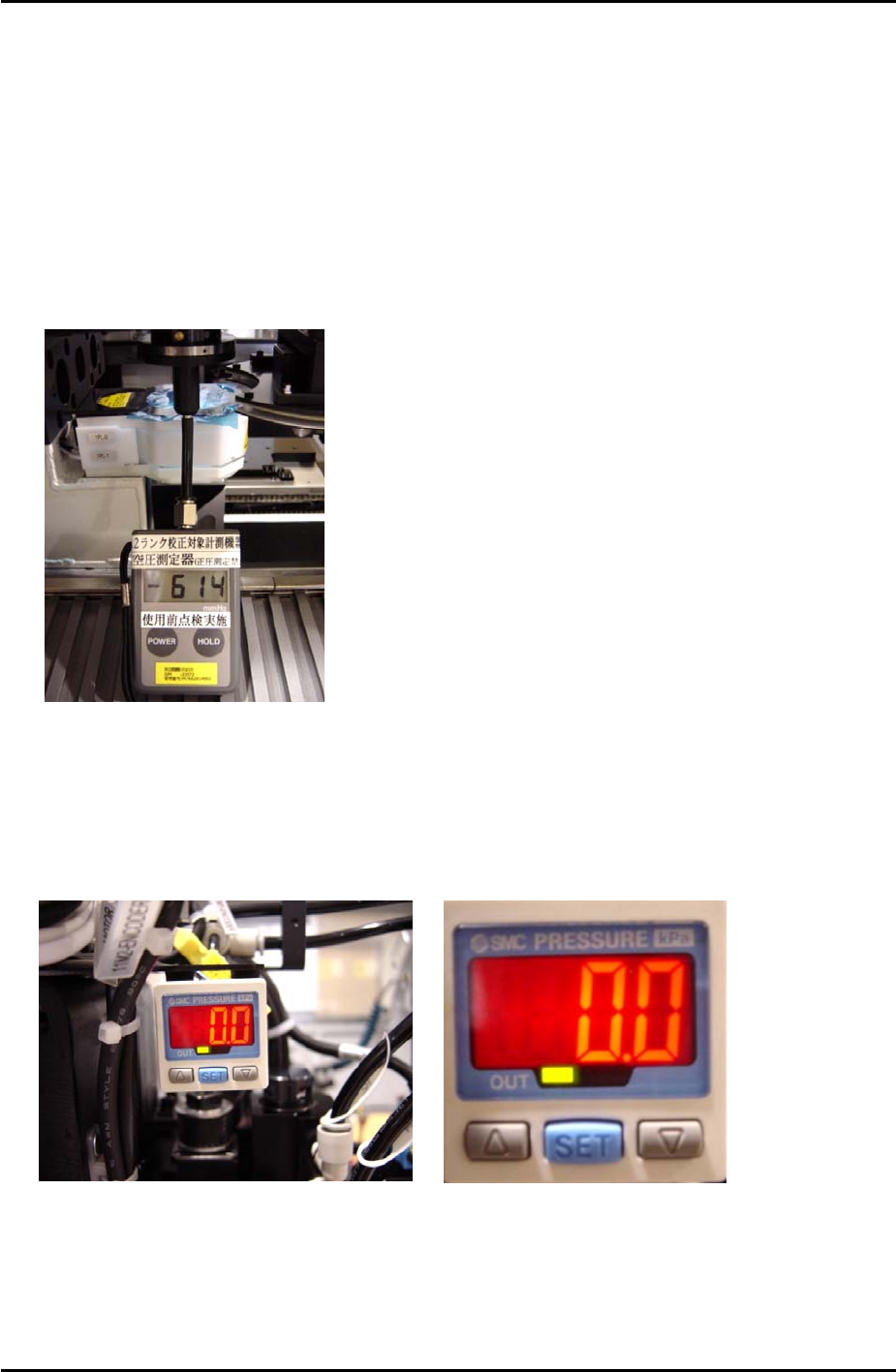
6. Attach the manometer to the nozzle jig. Turn Y021 NozzleUnhold OFF, and attach the
nozzle jig to the placing head. Turn I/O Y020 PartsPickUp ON. Under these conditions
the manometer should indicate the vaccuum pressure is –600mmHg (-79.99kPa) or more
negative.
7. Adjust the parts air blow speed controller. Turn Y01D PartsPickUpDes ON, and Y020
PartsPickUp OFF, then adjust the speed controller until the manometer indicates the air
blow pressure is +75 mmHg (9.99kPa).
SMC Pressure Sensor Setting
1. To unlock the pressure sensor, press and hold the [SET] button for more than 6 seconds.
Use the arrow keys to select unlock and then press [SET] to return to the original screen.
2. Press the [SET] button for more than 2 seconds.
Fuji Machine Mfg. Co., Ltd. Okazaki.
SMT Equipment Quality Assurance Dept.
5 – 12 CS Section