XP Type II 工程师培训手册 (2.0).pdf.pdf - 第66页
FK-9F98-34 XP T ype II Series T raining T ext for Service Engineers Edition 2.0 XP142E – Chapter 6 Proper Dat a Measurement s Page 7 of 30 5. Choose [SIDE1] from the “Camera’ drop down list and press [Focus Adjustment]. …
FK-9F98-34 XP Type II Series Training Text for Service Engineers
Edition 2.0 XP142E – Chapter 6 Proper Data Measurements Page 6 of 30
8. Add together the values recorded at steps 6 and 7, then divide the total by 2 to get the
average.
9. Adjust the “INTENS” volume screw and touch the image on the screen until the
brightness reading is at the average calculated in step 8. The intensity of the strobe light
power source is now exactly half way between its maximum and minimum.
10. Finally adjust the brightness gain on the top of the parts camera so that the brightness
reading is 120.
6.5 Parts Camera Focus Adjustment
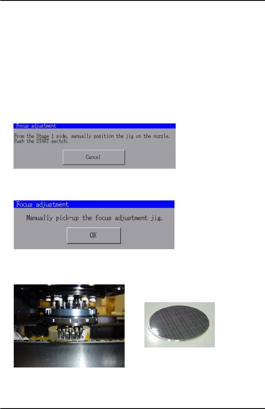
1. In [Maintenance Mode] select [Maintenance] – [Focus adjustment] and the following
message appears:
2. Press and hold down the [START] button until the following message displays:
3. Put the focus jig on the revolver with the patterned side facing downwards:
Focus jig
4. Once the focus jig is on the revolver press [OK].
Fuji Machine Mfg. Co., Ltd. Okazaki
SMT Equipment Quality Assurance Dept.
6 – 6 CS Section
FK-9F98-34 XP Type II Series Training Text for Service Engineers
Edition 2.0 XP142E – Chapter 6 Proper Data Measurements Page 7 of 30
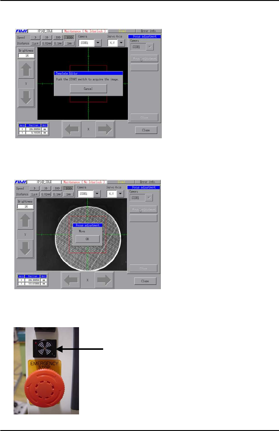
5. Choose [SIDE1] from the “Camera’ drop down list and press [Focus Adjustment]. The
following message appears:
6. Press and hold down the [START] button until the buzzer sounds and the red light
flashes. The following message appears:
7. Press [OK] and adjust the focus of the parts camera. When the focus is within range the
buzzer sounds and the red light flashes:
Buzzer
Fuji Machine Mfg. Co., Ltd. Okazaki
SMT Equipment Quality Assurance Dept.
6 – 7 CS Section
FK-9F98-34 XP Type II Series Training Text for Service Engineers
Edition 2.0 XP142E – Chapter 6 Proper Data Measurements Page 8 of 30
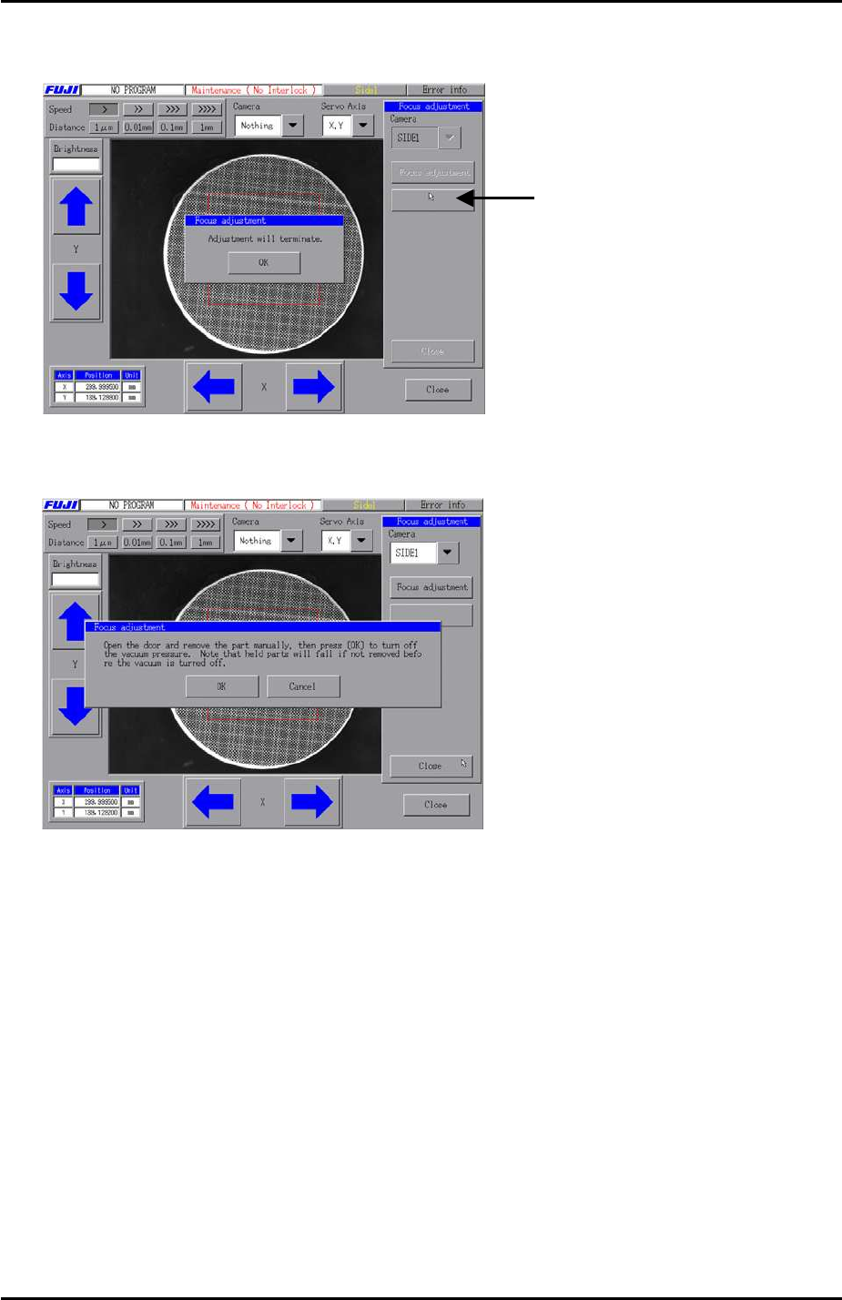
8. Once the focus has been set within range press the following tab to terminate the
adjustment:
9. Press [OK] and then [Close]. The following message appears:
Press here to terminate
the adjustment
10. Remove the focus jig by hand and then press [OK].
11. Repeat the procedure for side 2 to confirm the focus is also within range at side 2.
12. Finally lock the focus ring hollow bolt with loctite 425.
Fuji Machine Mfg. Co., Ltd. Okazaki
SMT Equipment Quality Assurance Dept.
6 – 8 CS Section