XP Type II 工程师培训手册 (2.0).pdf.pdf - 第243页
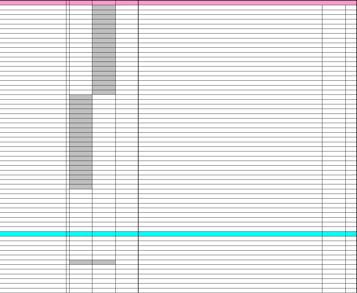
XP Proper Data ListType-II vol.3 Issue Date:2003/6/17 Item XP142 X P242 Input Rang e Explanation Editing Reboot __Camera1LeanRatio X = 00 None Sets the vertical angle of front camera 1. Calibration Data __Camera1LeanRati…
XP Proper Data ListType-II vol.3
Issue Date:2003/6/17
Item XP142
X
P242 Input Rang
e
Explanation
Editing
Reboot
f_MaxA = 1900000000 0
More than 0 Sets the maximum F-axis acceleration.
User Cannot Edit
f_ptpGain = 200 0
More than 0 Sets the gain during F-axis travel.
User Cannot Edit
f_stGain = 200 0
More than 0 Sets the gain during F-axis positioning.
User Cannot Edit
f_afterGain = 100 0
More than 0 Sets the gain during F-axis stop.
User Cannot Edit
f_P_CON_Start = 60
More than 0 Sets the F-axis P_CON start time (msec).
User Cannot Edit
f_integralGain = 100 0
More than 0 Sets the F-axis integral gain.
User Cannot Edit
f_AxisValid = 10
More than 0 F-axis enabled/disabled setting. 0:F-axis disabled (ignore), 1: F-axis enabled.
User Cannot Edit
f_spare2 = 10
More than 0 F-axis enabled/disabled setting. 0:F-axis disabled (ignore), 1: F-axis enabled.
User Cannot Edit
f_CurveNo = 10
More than 0 Specifies the F-axis cam curve number. 1: Distorted sine, 2:Cycloid curve, 3:NC2, etc.
User Cannot Edit
g_MaxV = 8500000 0
More than 0 Sets the maximum G-axis speed.
User Cannot Edit
g_Max
A
= 1900000000 0
More than 0 Sets the maximum G-axis acceleration.
User Cannot Edit
g_ptpGain = 200 0
More than 0 Sets the gain during G-axis travel.
User Cannot Edit
g_stGain = 200 0
More than 0 Sets the gain during G-axis positioning.
User Cannot Edit
g_afterGain = 100 0
More than 0 Sets the gain during G-axis stop.
User Cannot Edit
g_P_CON_Star
t
= 60
More than 0 Sets the G-axis P_CON start time (msec).
User Cannot Edit
g_integralGain = 100 0
More than 0 Sets the G-axis integral gain.
User Cannot Edit
g_AxisValid = 10
More than 0 G-axis enabled/disabled setting. 0:G-axis disabled (ignore), 1: G-axis enabled.
User Cannot Edit
g_spare2 = 10
More than 0 G-axis enabled/disabled setting. 0:G-axis disabled (ignore), 1: G-axis enabled.
User Cannot Edit
g_CurveNo = 10
More than 0 Specifies the G-axis cam curve number. 1: Distorted sine, 2:Cycloid curve, 3:NC2, etc.
User Cannot Edit
t_MaxV = 0 5000000
More than 0 Sets the maximum T-axis speed.
User Cannot Edit
t_MaxA = 0 100000000
More than 0 Sets the maximum T-axis acceleration.
User Cannot Edit
t_ptpGain = 050
More than 0 Sets the gain during T-axis travel.
User Cannot Edit
t_stGain = 0 1000
More than 0 Sets the gain during T-axis positioning.
User Cannot Edit
t_afterGain = 050
More than 0 Sets the gain during T-axis stop.
User Cannot Edit
t_P_CON_Start = 06
More than 0 Sets the T-axis P_CON start time (msec).
User Cannot Edit
t_integralGain = 050
More than 0 Sets the T-axis integral gain.
User Cannot Edit
t_AxisValid = 01
More than 0 T-axis enabled/disabled setting. 0:T-axis disabled (ignore), 1: T-axis enabled.
User Cannot Edit
t_spare2 = 01
More than 0 T-axis enabled/disabled setting. 0:T-axis disabled (ignore), 1: T-axis enabled.
User Cannot Edit
t_CurveNo = 02
More than 0 Specifies the T-axis cam curve number. 1: Distorted sine, 2:Cycloid curve, 3:NC2, etc.
User Cannot Edit
u_MaxV = 0 15000000
More than 0 Sets the maximum U-axis speed.
User Cannot Edit
u_Max
A
= 0 70000000
More than 0 Sets the maximum U-axis acceleration.
User Cannot Edit
u_ptpGain = 0 100
More than 0 Sets the gain during U-axis travel.
User Cannot Edit
u_stGain = 0 1000
More than 0 Sets the gain during U-axis positioning.
User Cannot Edit
u_afterGain = 050
More than 0 Sets the gain during U-axis stop.
User Cannot Edit
u_P_CON_Star
t
= 06
More than 0 Sets the U-axis P_CON start time (msec).
User Cannot Edit
u_integralGain = 040
More than 0 Sets the U-axis integral gain.
User Cannot Edit
u_AxisValid = 01
More than 0 U-axis enabled/disabled setting. 0:U-axis disabled (ignore), 1: U-axis enabled.
User Cannot Edit
u_spare2 = 01
More than 0 U-axis enabled/disabled setting. 0:U-axis disabled (ignore), 1: U-axis enabled.
User Cannot Edit
u_CurveNo = 01
More than 0 Specifies the U-axis cam curve number. 1: Distorted sine, 2:Cycloid curve, 3:NC2, etc.
User Cannot Edit
x_FeedforwardRatio = 00
0~100.0 Sets the multiplication ratio for feed forward control on the X-axis
Calibration Data
y_FeedforwardRati
o
= 00
0~100.0 Sets the multiplication ratio for feed forward control on the Y-axis
Calibration Data
z_FeedforwardRati
o
= 00
0~100.0 Sets the multiplication ratio for feed forward control on the Z-axis
Calibration Data
q_FeedforwardRatio = 00
0~100.0 Sets the multiplication ratio for feed forward control on the Q-axis
Calibration Data
r_FeedforwardRatio = 00
0~100.0 Sets the multiplication ratio for feed forward control on the R-axis
Calibration Data
f_FeedforwardRatio = 00
0~100.0 Sets the multiplication ratio for feed forward control on the F-axis
Calibration Data
g_FeedforwardRatio = 00
0~100.0 Sets the multiplication ratio for feed forward control on the G-axis
Calibration Data
t_FeedforwardRatio = 068
0~100.0 Sets the multiplication ratio for feed forward control on the T-axis
Calibration Data
u_FeedforwardRatio = 00
0~100.0 Sets the multiplication ratio for feed forward control on the U-axis
Calibration Data
_______CAMERA_OFFSET______
_
=
__Camera1Distance
X
= 101 68.5
None Sets the travel distance X from fiducial camera center to nozzle rotational center
Calibration Data
__Camera1Distance
Y
= 00
None Sets the travel distance Y from fiducial camera center to nozzle rotational center
Calibration Data
__Camera2Distance
X
= 101 68.5
None Sets the travel distance X from fiducial camera center to nozzle rotational center
Calibration Data
__Camera2Distance
Y
= 00
None Sets the travel distance Y from fiducial camera center to nozzle rotational center
Calibration Data
__DegFdclCam1Thet
a
= 00
None Sets the fiducial camera tilt relative to the servo axis.
Calibration Data
__DegFdclCam2Thet
a
= 00
None Not used
User Cannot Edit
__Camera1Center
X
= 00
None Sets the side 1 camera center position X (mm)
Calibration Data
__Camera1Center
Y
= 00
None Sets the side 1 camera center position y (mm)
Calibration Data
__Camera1Theta = 00
None Sets the side 1 camera tilt (deg)
Calibration Data
__Camera2Center
X
= 00
None Sets the side 2 camera center position X (mm)
Calibration Data
__Camera2Center
Y
= 00
None Sets the side 2 camera center position y (mm)
Calibration Data
__Camera2Theta = 00
None Sets the side 2 camera tilt (deg)
Calibration Data
6/12
XP Type-Ⅱ Proper Data List vol.3

XP Proper Data ListType-II vol.3
Issue Date:2003/6/17
Item XP142
X
P242 Input Rang
e
Explanation
Editing
Reboot
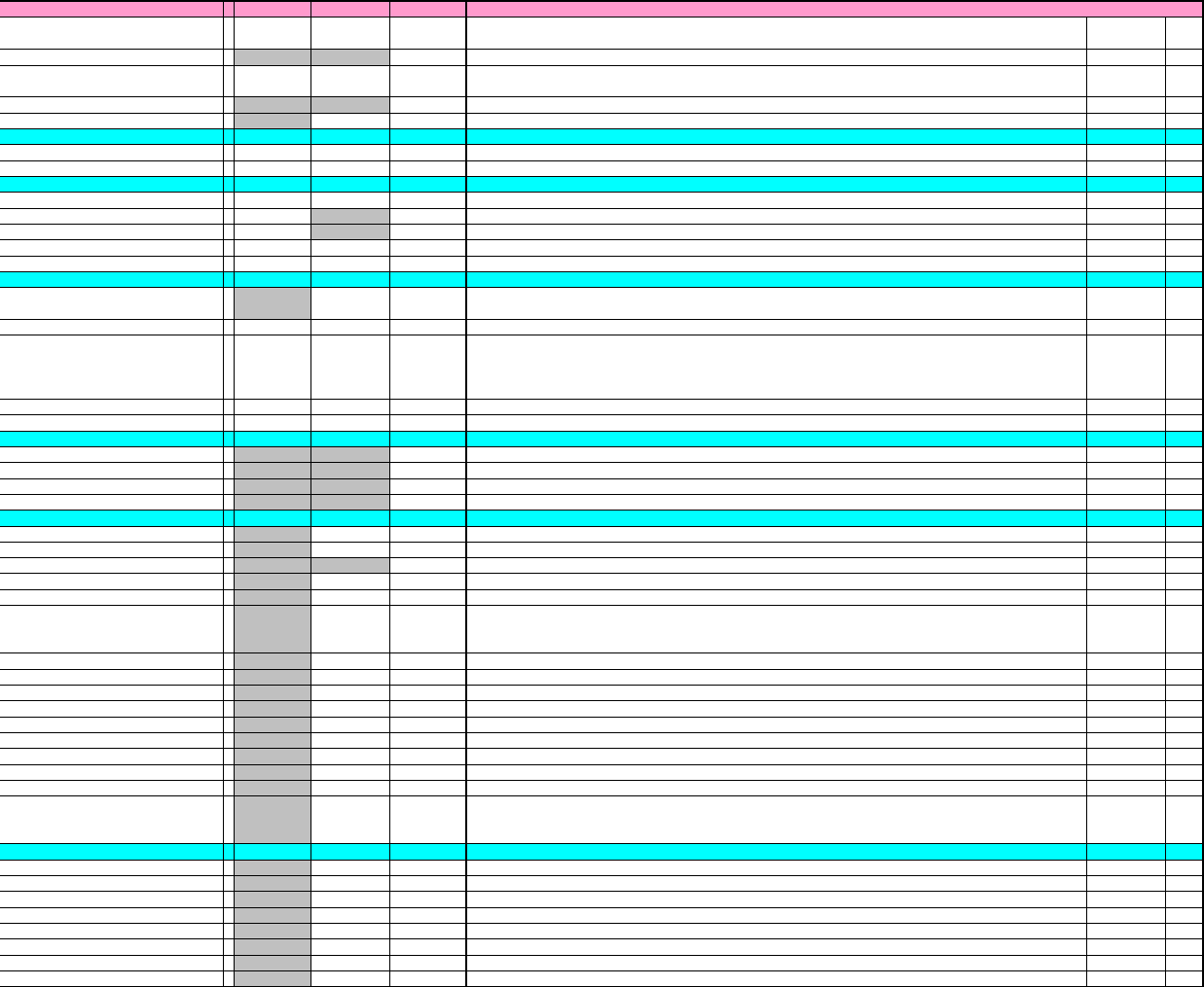
__Camera1LeanRatio
X
= 00
None Sets the vertical angle of front camera 1.
Calibration Data
__Camera1LeanRatio
Y
= 00
None Sets the vertical angle of front camera 1.
Calibration Data
__Camera2LeanRatio
X
= 00
None Sets the vertical angle of front camera 2.
Calibration Data
__Camera2LeanRatio
Y
= 00
None Sets the vertical angle of front camera 2.
Calibration Data
_______MACHINE_ORIGIN_____
_
=
X_Stage1org = 412.1 436.5
None Sets the stage 1 origin X (mm)
Calibration Data
Y_Stage1org = 87
None Sets the stage 1 origin Y (mm)
Calibration Data
X_Stage2org = 422.9 557.5
None Sets the stage 2 origin X (mm)
Calibration Data
Y_Stage2org = 805 842
None Sets the stage 2 origin Y (mm)
Calibration Data
X_Stage3org = 00
None Sets the stage 3 origin X (mm)
User Cannot Edit
Y_Stage3org = 00
None Sets the stage 3 origin Y (mm)
User Cannot Edit
X_Stage4org = 00
None Sets the stage 4 origin X (mm)
User Cannot Edit
Y_Stage4org = 00
None Sets the stage 4 origin Y (mm)
User Cannot Edit
Z_Stage1Surface = 0.7 14.3
None Sets the stage 1 origin (height) (mm)
Calibration Data
Z_Stage2Surface = 0.7 0.8
None Sets the stage 2 origin (height) (mm)
Calibration Data
Z_Stage3Surface = 00
None Sets the stage 3 origin (height) (mm)
User Cannot Edit
Z_Stage4Surface = 00
None Sets the stage 4 origin (height) (mm)
User Cannot Edit
__DevPitch1 = 16 20
None Specifies the device pitch (Stage 1). 16:16mm pitch, 20:20mm pitch.
User Cannot Edit
__DevPitch2 = 16 20
None Specifies the device pitch (Stage 2). 16:16mm pitch, 20:20mm pitch.
User Cannot Edit
__DevPitch3 = 00
None Specifies the device pitch (Stage 3). 16:16mm pitch, 20:20mm pitch.
User Cannot Edit
__DevPitch4 = 00
None Specifies the device pitch (Stage 4). 16:16mm pitch, 20:20mm pitch.
User Cannot Edit
X_BoardOrg = 466.5 471.5
None Sets the panel origin X (counter value)
Calibration Data
Y_BoardOrg = 236.25 242.3
None Sets the panel origin Y (counter value)
Calibration Data
Z_BoardSurface = 0.7 1
None Sets the panel surface height (counter value)
Calibration Data
X_TableOrg = 550
None Specifies the X-axis counter value at head retract position. 5:5mm, 50:50mm
User Cannot Edit
Y_TableOrg = 400 350
None Specifies the Y-axis counter value at head retract position. 350:350mm, 400:400mm
User Cannot Edit
F_UpPoin
t
= 00
None Set F-axis UP limit (counter value)
Calibration Data
F_DownPoin
t
= -8.5 0
None Set F-axis DOWN limit (counter value)
Calibration Data
G_UpPoint = 00
None Set G-axis UP limit (counter value)
Calibration Data
G_DownPoin
t
= -8.5 0
None Set G-axis DOWN limit (counter value)
Calibration Data
R_Pos1 = 00
None Sets the revolver angle when nozzle 1 is at pickup position.
User Cannot Edit
Q_PosPick1 = 6.5 0
None Sets the Q-axis pickup angle when nozzle 1 is at the pickup position.
User Cannot Edit
Q_PosPlace1 = 00
None Sets the Q-axis placing position when nozzle 1 is at "R_POS1" position.
User Cannot Edit
Z_DoubleMotionPoin
t
7.5 0
None Z-axis double motion placement stopping height (mm)
Calibration Data
______NOZZLE_POSITION_____
_
=
X_NzlPosX1 = 085
None Sets the nozzle position (1) X (mm)
Calibration Data
Y_NzlPosY1 = 0 789.5
None Sets the nozzle position (1) Y (mm)
Calibration Data
Z_NzlPosZ1 = 0 0.7
None Sets the nozzle position (1) Z (mm)
Calibration Data
Z_NzlPosZH = 15.6 52
None Sets the maximum height when picking up nozzle.
Calibration Data
X_RemoverPos = 0 110
None Sets the X-coordinate of remover for tray unloading (mm).
Calibration Data
Y_RemoverPos = 0 1093
None Sets the Y-coordinate of remover for tray unloading (mm).
Calibration Data
Z_RemoverPos = 00
None Sets the Z-coordinate of remover for tray unloading (mm).
Calibration Data
__NzlPosOffsetX1 = 00
None Sets the nozzle center position offset X (1).
Calibration Data
__NzlPosOffsetY1 = 00
None Sets the nozzle center position offset Y (1).
Calibration Data
__NzlPosOffsetX2 = 00
None Sets the nozzle center position offset X (2).
Calibration Data
__NzlPosOffsetY2 = 00
None Sets the nozzle center position offset Y (2).
Calibration Data
__NzlPosOffsetX3 = 00
None Sets the nozzle center position offset X (3).
Calibration Data
__NzlPosOffsetY3 = 00
None Sets the nozzle center position offset Y (3).
Calibration Data
__NzlPosOffsetX4 = 00
None Sets the nozzle center position offset X (4).
Calibration Data
__NzlPosOffsetY4 = 00
None Sets the nozzle center position offset Y (4).
Calibration Data
__NzlPosOffsetX
5
= 00
None Sets the nozzle center position offset X (5).
Calibration Data
__NzlPosOffsetY
5
= 00
None Sets the nozzle center position offset Y (5).
Calibration Data
__NzlPosOffsetX6 = 00
None Sets the nozzle center position offset X (6).
Calibration Data
__NzlPosOffsetY6 = 00
None Sets the nozzle center position offset Y (6).
Calibration Data
__NzlPosOffsetX7 = 00
None Sets the nozzle center position offset X (7).
Calibration Data
__NzlPosOffsetY7 = 00
None Sets the nozzle center position offset Y (7).
Calibration Data
__NzlPosOffsetX
8
= 00
None Sets the nozzle center position offset X (8).
Calibration Data
__NzlPosOffsetY
8
= 00
None Sets the nozzle center position offset Y (8).
Calibration Data
__NzlPosOffsetX
9
= 00
None Sets the nozzle center position offset X (9).
Calibration Data
__NzlPosOffsetY
9
= 00
None Sets the nozzle center position offset Y (9).
Calibration Data
______DISPOSE_POSITION____
_
=
7/12
XP Type-Ⅱ Proper Data List vol.3
XP Proper Data ListType-II vol.3
Issue Date:2003/6/17
Item XP142
X
P242 Input Rang
e
Explanation
Editing
Reboot
X_Disposal1 = 346.5 351.5
None
S
e
t
s
th
e
X
-coor
di
na
t
e pos
iti
on
f
or
di
scar
di
ng sma
ll
s
i
ze re
j
ec
t
par
t
s
i
n
th
e re
j
ec
t
b
ox
(
mar
k
camera
reference).
Calibration Data
X_Disposal2 = 00
None Not used
Calibration Data
Y_Disposal1 = 202.4 206
None
S
e
t
s
th
e
Y
-coor
di
na
t
e pos
iti
on
f
or
di
scar
di
ng sma
ll
s
i
ze re
j
ec
t
par
t
s
i
n
th
e re
j
ec
t
b
ox
(
mar
k
camera
reference).
Calibration Data
Y_Disposal2 = 00
None Not used
Calibration Data
Z_Disposal2 = 01
None Sets the Z-coordinate position for discarding large size reject parts in the reject box.
Calibration Data
_______PRIZM_POSITION_____
_
=
__PrismFront = 136.5 147
None Sets the side 1 camera's image acquisition position (mm)
Calibration Data
__PrismBack = 676.5 687
None Sets the side 2 camera's image acquisition position (mm)
Calibration Data
________JIG_POSITION______
_
=
X_JigPickPos1 = 127.5 157.1
None Sets the XP-142E jig's (large) X-coordinate pickup position, XP242E jig's X-coordinate pickup position.
Calibration Data
X_JigPickPos2 = 137.5 0
None Sets the XP-142E jig's (medium) X-coordinate pickup position.
Calibration Data
X_JigPickPos3 = 147.5 0
None Sets the XP-142E jig's (small) X-coordinate pickup position.
Calibration Data
Y_JigPickPos = 209.05 207.75
None Sets the jig's Y-coordinate pickup position.
Calibration Data
Z_JigPickPos = 0.7 3.5
None Sets the jig's Z-coordinate pickup height.
Calibration Data
_________ELEGANCE_________
_
=
__PlaceEleganceQ = 00
0~1.00
S
e
t
s
th
e
Q
-ax
i
s acce
l
era
ti
on
(0
.
01
t
o
1)
a
t
XP
-
242E
p
l
acemen
t
opera
ti
on.
Wh
en se
t
t
o
"0"
, a se
tti
ng o
f
1
.
0
is adopted.
User Cannot Edit
__PlaceUpSpeedRati
o
= 0.05 0.05
0~1.00 XP-242E speed coefficient for UP motion after placement. (Applies only for Vision Types 100 and 20).
User Can Edit
__PlaceUpMaxSpeed = 1500 1500
<TypeI>
0~1000.0
<TypeII>
0~1500.0 Maximum speed reference for Z-axis speed after part placement.
User Can Edit
__CycleStealEleganc
e
= 11
0.01~1.00 Set the elegance value for the cycle steal after the time set at "_CycleStealTime" elapses.
User Can Edit
__MainteMaxVRatio = 0.1 0.1
0.01~1.00 Specifies the speed ration when in maintenance mode.
User Cannot Edit
_______F_GLASS_VALUE______
_
=
XMainStDecelPo
s
= 00
None Panel deceleration point (X-axis).
User Cannot Edit
YMainStDecelPo
s
= 00
None Panel deceleration point (Y-axis).
User Cannot Edit
XMainStArrivPos = 00
None Panel arrival point (X-axis).
User Cannot Edit
YMainStArrivPos = 00
None Panel arrival point (Y-axis).
User Cannot Edit
___________TRAY___________
_
=
T_TrayOrg = 0 465
None Sets the T-axis position (shuttle advance enabled position) fror tray position 101.
Calibration Data
T_TrayEmptyOrg = 0 495
None Sets the T-axis position where a "no tray at tray position 101" judgement is made.
Calibration Data
U_ShuttleBackwardOfs
t
= 00
None Sets the shuttle retract limit offset (mm).
Calibration Data
U_ShuttleForwardOfs
t
= 00
None Sets the shuttle advance limit offset (mm).
Calibration Data
U_ShuttleClampPo
s
= 0 526
None Sets the shuttle clamp position (mm).
Calibration Data
__ShuttleClampOfst = 00
-
1.5000~1.5
000
Set the offset (mm) for the clamp stroke of the tray shuttle. This setting is only valid for machines with
upgraded tray units (when "_TrayUnitType" has been set to "1").
Calibration Data
__ElevotorOfst2 = 00
None Sets the T-axis position offset (mm) when a 11* tray can be extended.
Calibration Data
__ElevotorOfst3 = 00
None Sets the T-axis position offset (mm) when a 12* tray can be extended.
Calibration Data
__ElevotorOfst4 = 00
None Sets the T-axis position offset (mm) when a 13* tray can be extended.
Calibration Data
__ElevotorOfst5 = 00
None Sets the T-axis position offset (mm) when a 14* tray can be extended.
Calibration Data
__ElevotorOfst6 = 00
None Sets the T-axis position offset (mm) when a 15* tray can be extended.
Calibration Data
__ElevotorOfst7 = 00
None Sets the T-axis position offset (mm) when a 16* tray can be extended.
Calibration Data
__ElevotorOfst8 = 00
None Sets the T-axis position offset (mm) when a 17* tray can be extended.
Calibration Data
__ElevotorOfst9 = 00
None Sets the T-axis position offset (mm) when a 18* tray can be extended.
Calibration Data
__ElevotorOfst10 = 00
None Sets the T-axis position offset (mm) when a 19* tray can be extended.
Calibration Data
__TrayPickUpOfstZ = 00
-
3.0000~3.0
000
Set the offset (mm) for the pickup height of tray parts. However, no offset is performed if this value is set
below -0.3 or above +0.3.
User Can Edit
________PLACE_OFFSET______
_
=
__PlaceGlobalOfst
X
= 00
None Sets the placement global offset X (valid only for Vision Types 10, 18, 20).
User Cannot Edit
__PlaceGlobalOfst
Y
= 00
None Sets the placement global offset Y (valid only for Vision Types 10, 18, 20).
User Cannot Edit
__PlaceGlobalOfst
Q
= 00
None Sets the placement global offset Q (valid only for Vision Types 10, 18, 20).
User Cannot Edit
__PlaceGlobalOfstX
R
= 00
None Sets the placement global offset X (valid only for Vision Types 10, 18, 20).
User Cannot Edit
__PlaceGlobalOfstY
R
= 00
None Sets the placement global offset Y (valid only for Vision Types 10, 18, 20).
User Cannot Edit
__PlaceGlobalOfstQ
R
= 00
None Sets the placement global offset Q (valid only for Vision Types 10, 18, 20).
User Cannot Edit
__PlaceOfstForFidCamAng
X
= 00
None Sets the placement global offset X (mm).
User Cannot Edit
__PlaceOfstForFidCamAng
Y
= 00
None Sets the placement global offset Y (mm).
User Cannot Edit
8/12
XP Type-Ⅱ Proper Data List vol.3