XP Type II 工程师培训手册 (2.0).pdf.pdf - 第183页
FK-9F98-34 XP T ype II Series T raining T ext for Service Engineers Edition 2.0 XP242E – Chapter 6 Proper Data Mea surement s Page 28 of 30 8. Set the conveyor width to minimum, then select [Manual Operation] – [Conveyor…
FK-9F98-34 XP Type II Series Training Text for Service Engineers
Edition 2.0 XP242E – Chapter 6 Proper Data Measurements Page 27 of 30
recorded in step 6. The difference in value should be within 0.5mm. This ensures
that the X-axis and the glass gage are parallel.
9. With the fiducial camera still centered on the last dot in the bottom right hand corner
of the glass gage select [Maintenance C] – [Matrix data measurement] – and set
the acceleration rate to 1.0 before selecting [Start].
10. The measurement will take approximately 20 minutes to complete. Matrix data
measurement is designed to compensate for minute discrepancies in the
straightness of the X and Y- axis ball screws. The measurement is performed in the
factory prior to machine shipment and is not normally performed again.
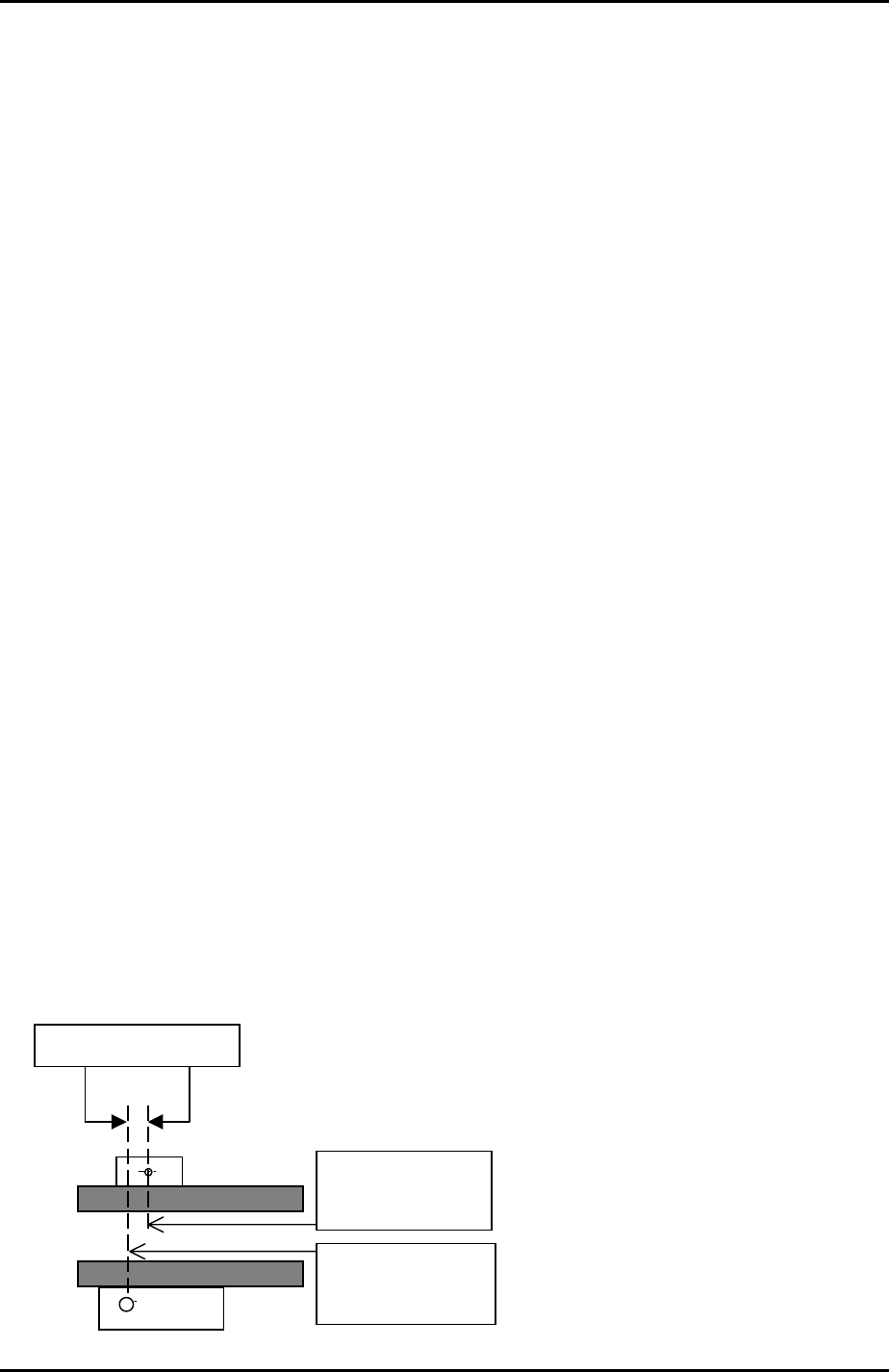
6.19 Conveyor Automatic Width Changer
1. Set the conveyor width to approximately 100mm.
2. Select [Maintenance A] – [Jog] – [Fiducial] – and display the cross hairs on the
screen.
3. Center the fiducial camera on the glass gage station fiducial mark and record the X-
axis counter value at this position.
4. Inch the fiducial camera in the Y direction until the width defining bracket comes
into view, then center the camera on the width defining mark.
5. Record the X-axis counter value at this position and subtract this figure from the X
axis counter value recorded in step 3. This value is the “ConvWidthMarkDiffX”
proper data.
6. Select [Maintenance C] – [Proper Data Editor] – [Others] – [ConvWidthMarkDiffX] –
and manually input the figure calculated at step 5.
7. In the following example the ConvWidthMarkDiffX would be 1mm:
X-axis counter:
135.000 mm
ConvWidthMarkDiffX
X-axis counter:
136.000 mm
Fuji Machine Mfg. Co., Ltd. Okazaki.
SMT Equipment Quality Assurance Dept.
6 – 27 CS Section
FK-9F98-34 XP Type II Series Training Text for Service Engineers
Edition 2.0 XP242E – Chapter 6 Proper Data Measurements Page 28 of 30
8. Set the conveyor width to minimum, then select [Manual Operation] – [Conveyor
Width] – [Measure Speed] – [START]. After the calibration is complete press [YES]
to save the results in proper data (ConvWidthMtrSpeed).
9. Once speed measurement is complete input a board width and select [Move] –
[START]. The conveyor automatically moves to this board width.
10. Select a board with the same width as that input in step 9 and place it in the
conveyor. The board should fit smoothly into the conveyor, and there should be a
clearance of 0.5mm between conveyor and board. If not it is necessary to measure
an offset.
11. Use the conveyor width changer inching tabs to change the conveyor width until the
clearance between board and conveyor is 0.5mm then select [Measure Offset].
After the calibration is complete press [YES] to save the results in proper data
(ConvWidthOffset).
6.20 Corner Dog
1. Select [Maintenance C] – [Proper Data Editor] – [MACHINE_TYPE] –
[CornerRearSide] – and set to “2”.
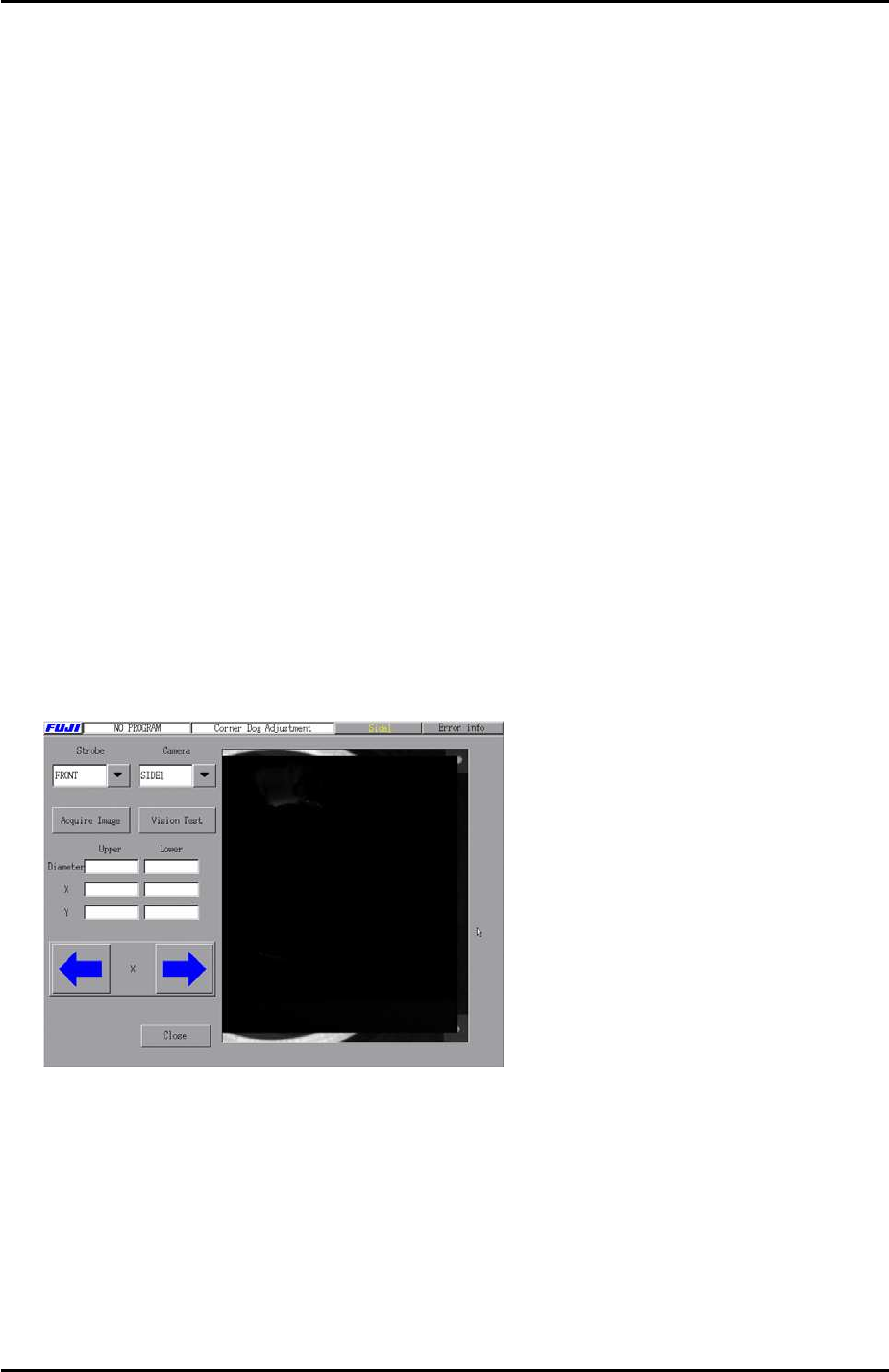
2. Select [Maintenance C] – [Custom Maintenance] – [Maintenance] – [Corner Dog
Adjustment] and the following screen displays:
3. Select [Acquire Image] – and hold down the [START] button until the image is
acquired.
Fuji Machine Mfg. Co., Ltd. Okazaki.
SMT Equipment Quality Assurance Dept.
6 – 28 CS Section
FK-9F98-34 XP Type II Series Training Text for Service Engineers
Edition 2.0 XP242E – Chapter 6 Proper Data Measurements Page 29 of 30
4. Adjust the position of the corner dog so that the two marks on the corner dog
bracket appear within the borders of the green search area as shown below:
5. Select [SIDE 2] – [Acquire Image] – and hold down [START] to confirm that the two
marks on the corner dog bracket appear within the borders of the green search
area at the side 2 camera.
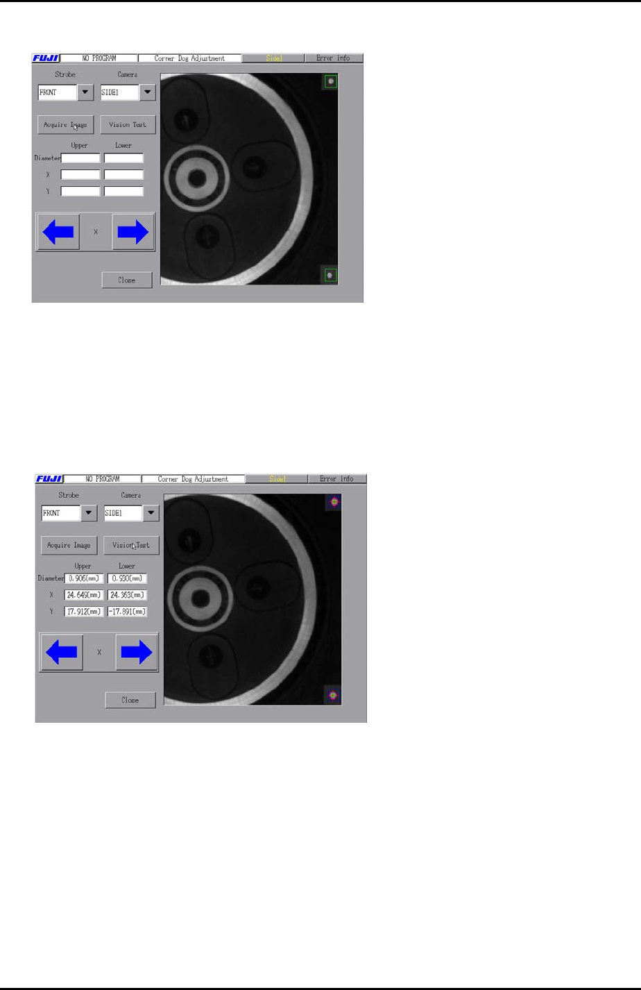
6. After adjusting the position of the corner dog within the borders of the green search
area select [Vision Test] to confirm that the corner dog can be vision processed. If
vision processing is successful trace lines will appear on the corner dog as shown
in the photo below:
Fuji Machine Mfg. Co., Ltd. Okazaki.
SMT Equipment Quality Assurance Dept.
6 – 29 CS Section