XP Type II 工程师培训手册 (2.0).pdf.pdf - 第58页
FK-9F98-34 XP T ype II Series T raining T ext for Service Engineers Edition 2.0 XP142E – Chapter 5 Peripheral Adjustm ents Page 14 of 14 NOTES: Fuji Machine Mfg. Co., Ltd. Okazaki SMT Equipment Quality Assurance Dept. 5 …
FK-9F98-34 XP Type II Series Training Text for Service Engineers
Edition 2.0 XP142E – Chapter 5 Peripheral Adjustments Page 13 of 14
Air Blow Pressure Check
1. Select [Maintenance A] – [I/O Check] – [Y01F ResetCylinder] – [ON] to raise the parts
vacuum pin and the air blow pin.
2. Select [Maintenance A] – [I/O check] – [Y01F ResetCylinder] – [OFF] to lower the reset
cylinder.
3. Attach the nozzle, air tube and manometer at nozzle position 1.
4. Align the pusher above the nozzle number 1 piston and descend the Z-axis using the
pusher to push down the vacuum pin and the air blow pin.
5. Select [Maintenance A] – [I/O check] – [Y016 VacuumPump] – [ON] and [Y01D
partspickUpDes] – [ON] and check the air blow pressure. Adjust the air regulator at side
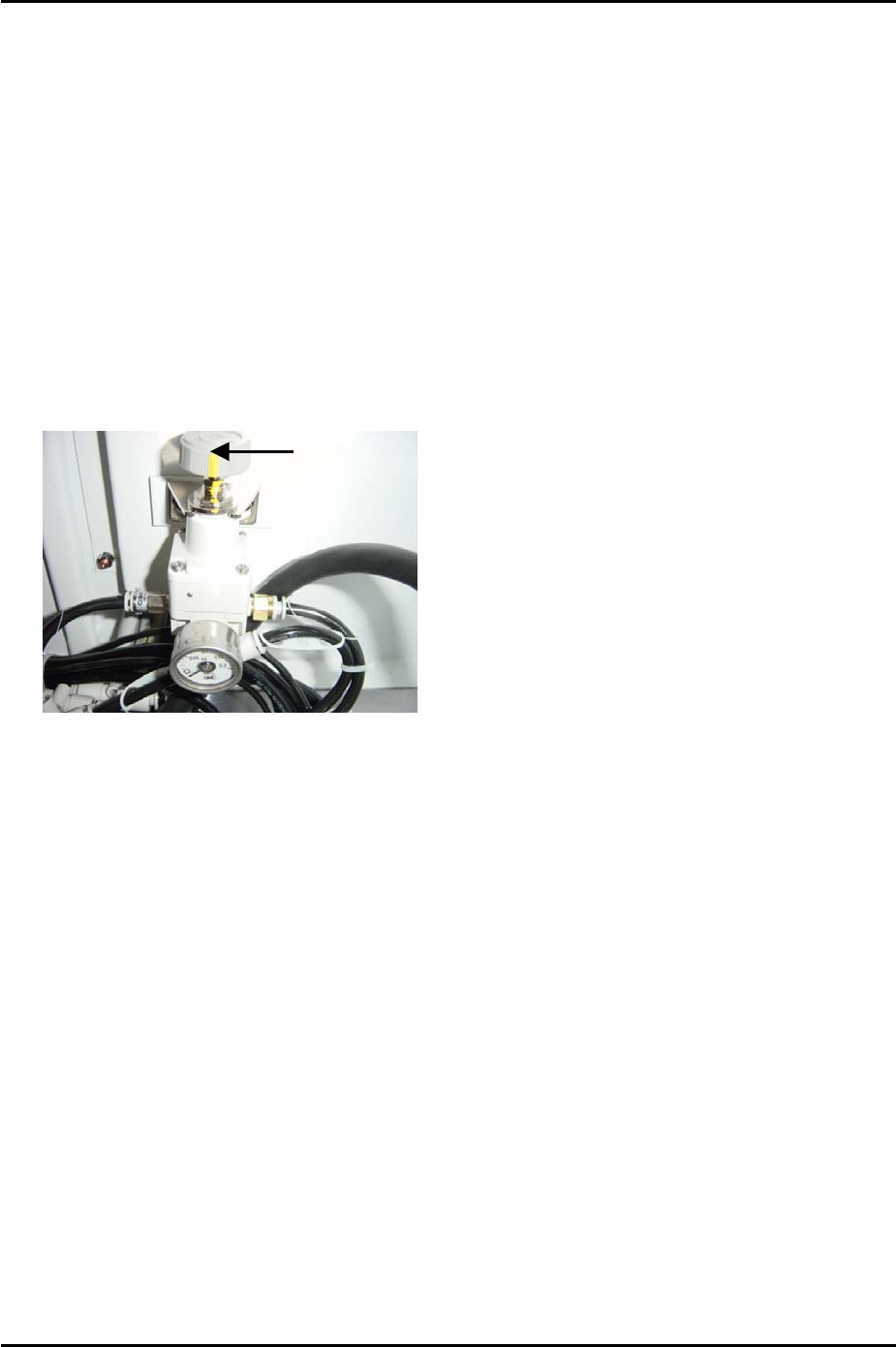
2 until the pressure reading is 110 +/- 10 mmHg (14.67 +/- 1.33 kPa).
Adjust Here
6. Finally lock the air regulator.
Fuji Machine Mfg. Co., Ltd. Okazaki
SMT Equipment Quality Assurance Dept.
5 – 13 CS Section

FK-9F98-34 XP Type II Series Training Text for Service Engineers
Edition 2.0 XP142E – Chapter 5 Peripheral Adjustments Page 14 of 14
NOTES:
Fuji Machine Mfg. Co., Ltd. Okazaki
SMT Equipment Quality Assurance Dept.
5 – 14 CS Section

C
C
h
h
a
a
p
p
t
t
e
e
r
r
6
6
P
P
r
r
o
o
p
p
e
e
r
r
D
D
a
a
t
t
a
a
M
M
e
e
a
a
s
s
u
u
r
r
e
e
m
m
e
e
n
n
t
t
s
s