XP Type II 工程师培训手册 (2.0).pdf.pdf - 第64页
FK-9F98-34 XP T ype II Series T raining T ext for Service Engineers Edition 2.0 XP142E – Chapter 6 Proper Dat a Measurement s Page 5 of 30 6.4 Part s Camera Brightness Adjustment 1. Select [Maintenance C] – [Custom Maint…
FK-9F98-34 XP Type II Series Training Text for Service Engineers
Edition 2.0 XP142E – Chapter 6 Proper Data Measurements Page 4 of 30
5. The prism should be flat to within 0.01mm. If necessary adjust so that it is flat.
6. If the flatness of the side 1 prism has been adjusted, select the [Side1] camera and inch
the revolver above the center of the side 1 light source. Readjust the tilt of the camera in
the Y direction until the horizontal cross hair is aligned with the revolver center.
7. Select the [Side2] camera and inch the revolver above the center of the side 2 light
source. The horizontal cross hair should be aligned with the revolver center. If not align
the horizontal cross hair with the revolver center by adjusting the tilt of the side 2 prism.
8. Finally lock all bolts loosened during the adjustment.
6.3 Prism Position
1. In [Maintenance Mode] inch the revolver above the center of the side 1 light source and
select the [Side1] camera to display the live image.
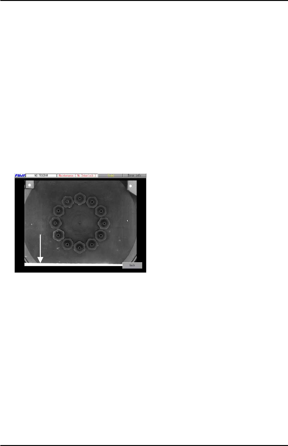
2. Press [Full Screen] and check the image on the monitor. In the following example the
light source is still visible at the bottom of the screen:
Light
Source
3. Inch the Y axis until the light source is no longer visible in the [Full Screen] image then
record the Y axis counter value at that position.
4. Select [Maintenance] – [Proper Data Editor] – [PRIZM POSITION] – [PrismFront] – and
input the counter value recorded in step 3.
5. Repeat the procedure for the side 2 prism position [PrismBack].
Fuji Machine Mfg. Co., Ltd. Okazaki
SMT Equipment Quality Assurance Dept.
6 – 4 CS Section
FK-9F98-34 XP Type II Series Training Text for Service Engineers
Edition 2.0 XP142E – Chapter 6 Proper Data Measurements Page 5 of 30
6.4 Parts Camera Brightness Adjustment
1. Select [Maintenance C] – [Custom Maintenance] - [Maintenance] – [I/O Check] – [Y016
VacuumPump] – [ON], lower all the vacuum pins and then attach the color sample to the
revolver with the grey surface facing downwards. Inch the color sample above the center
of the side 1 light source:
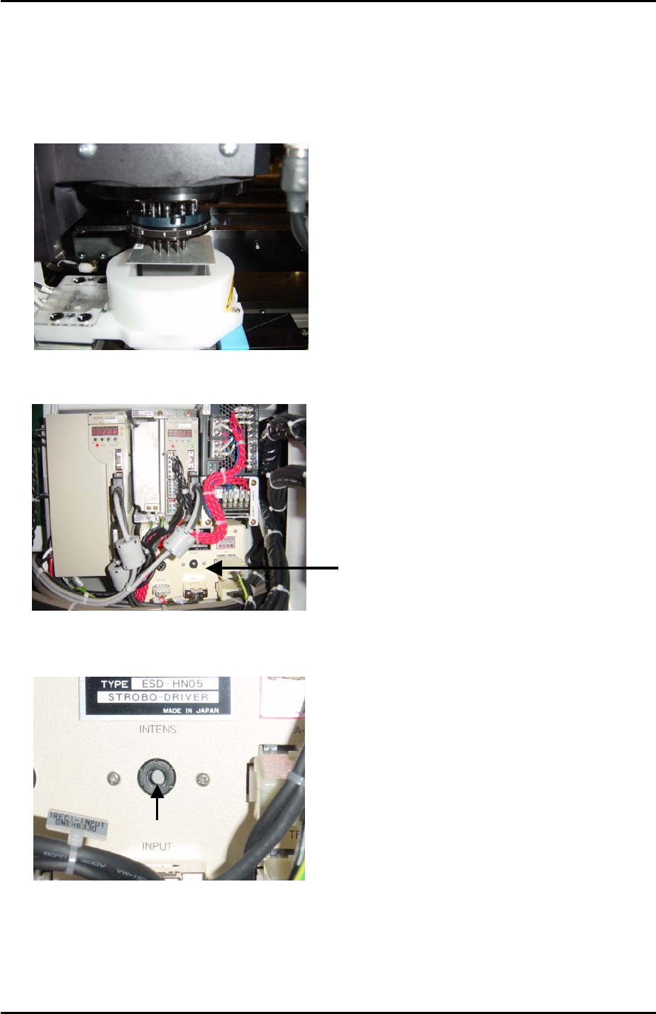
2. Locate the strobe light power source in the side 1 electrical box:
3. Use a minus driver to turn the “INTENS” volume screw fully clockwise.
Strobe Light
Power Source
Volume Adjustment
6. Select the [SIDE1] camera and touch the screen to display a brightness reading. Record
this value.
7. Now turn the “INTENS” volume screw fully anti-clockwise and touch the image of the
color sample on the display to get a second brightness reading. Record this value.
Fuji Machine Mfg. Co., Ltd. Okazaki
SMT Equipment Quality Assurance Dept.
6 – 5 CS Section
FK-9F98-34 XP Type II Series Training Text for Service Engineers
Edition 2.0 XP142E – Chapter 6 Proper Data Measurements Page 6 of 30
8. Add together the values recorded at steps 6 and 7, then divide the total by 2 to get the
average.
9. Adjust the “INTENS” volume screw and touch the image on the screen until the
brightness reading is at the average calculated in step 8. The intensity of the strobe light
power source is now exactly half way between its maximum and minimum.
10. Finally adjust the brightness gain on the top of the parts camera so that the brightness
reading is 120.
6.5 Parts Camera Focus Adjustment
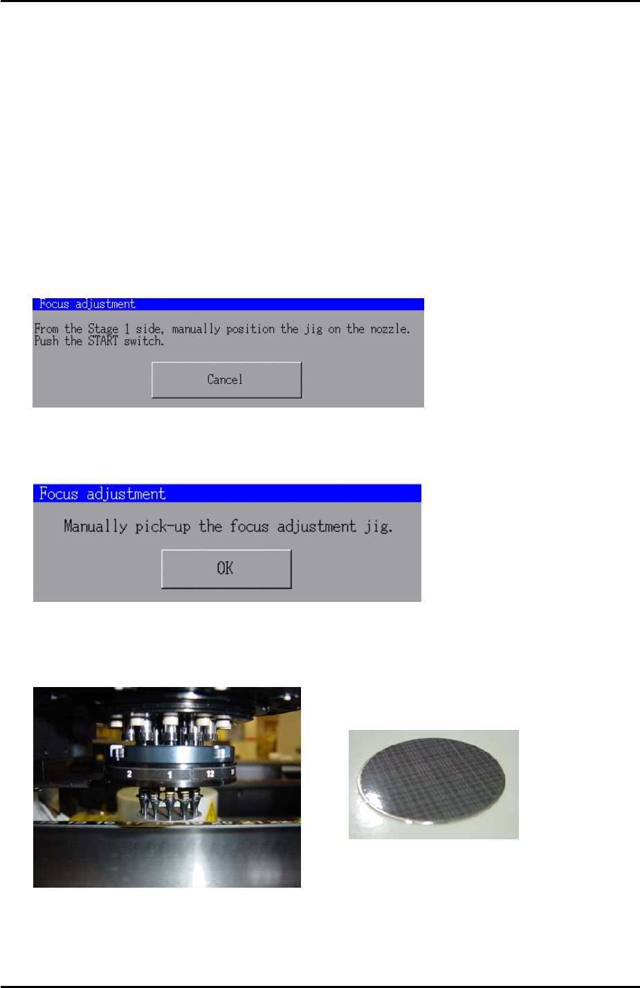
1. In [Maintenance Mode] select [Maintenance] – [Focus adjustment] and the following
message appears:
2. Press and hold down the [START] button until the following message displays:
3. Put the focus jig on the revolver with the patterned side facing downwards:
Focus jig
4. Once the focus jig is on the revolver press [OK].
Fuji Machine Mfg. Co., Ltd. Okazaki
SMT Equipment Quality Assurance Dept.
6 – 6 CS Section