XP Type II 工程师培训手册 (2.0).pdf.pdf - 第35页
FK-9F98-34 XP T ype II Series T raining T ext for Service Engineers Edition 2.0 XP142E – Chapter 4 Loader Adjustment Page 4 of 12 Post Adjustment Checks: 1. Ensure that the clamper motion is smooth when the main table is…
FK-9F98-34 XP Type II Series Training Text for Service Engineers
Edition 2.0 XP142E – Chapter 4 Loader Adjustment Page 3 of 12
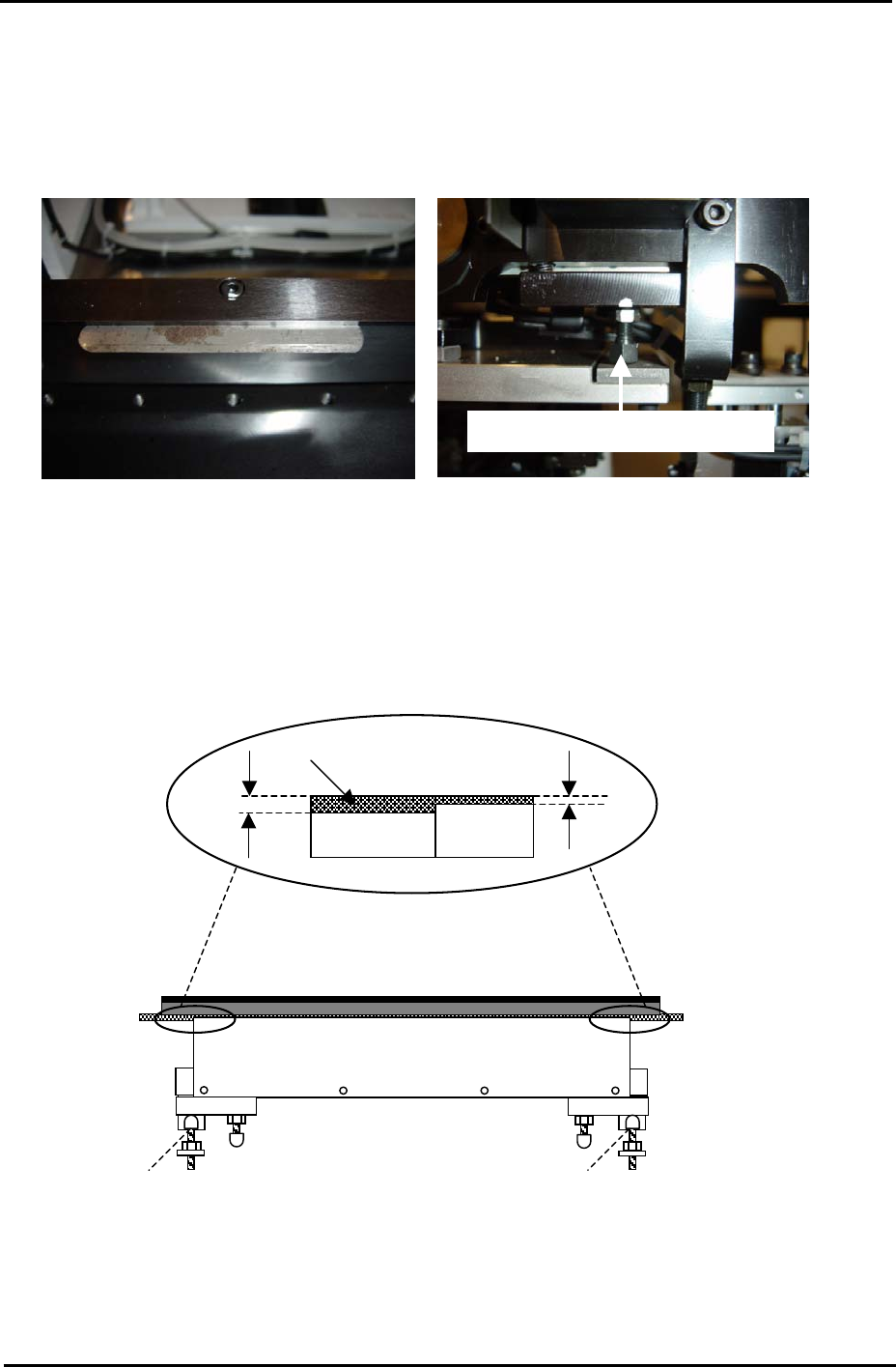
4.2 Board Clamper
1. Use the clamper height adjustment bolts to set the height of the clamper plate so that
there is a gap of 0.03mm between the top of the clamper plate and the conveyor rail.
0.03mm feeler gage
Clamper height adjustment bolt
2. Lower the lifter plate.
3. Adjust the position of the stoppers so that the lifter plate rests 0.5mm below the top
surface of the conveyor belt.
4. Refer to the diagram below and adjust the stoppers for both the fixed and adjustable rails:
Lifter Plate
Conveyor
Belt
0.5mm
1.0mm
Stopper Stopper
Fuji Machine Mfg. Co., Ltd. Okazaki.
SMT Equipment Quality Assurance Dept.
4 – 3 CS Section

FK-9F98-34 XP Type II Series Training Text for Service Engineers
Edition 2.0 XP142E – Chapter 4 Loader Adjustment Page 4 of 12
Post Adjustment Checks:
1. Ensure that the clamper motion is smooth when the main table is raised and lowered.
2. Ensure there is sufficient clearance between the back-up pins and the under side of a
clamped board.
3. Confirm that the minimum (0.5mm) thick board and the maximum (4.0mm) board can be
clamped correctly.
Fuji Machine Mfg. Co., Ltd. Okazaki.
SMT Equipment Quality Assurance Dept.
4 – 4 CS Section
FK-9F98-34 XP Type II Series Training Text for Service Engineers
Edition 2.0 XP142E – Chapter 4 Loader Adjustment Page 5 of 12
Fuji Machine Mfg. Co., Ltd. Okazaki.
SMT Equipment Quality Assurance Dept.
4 – 5 CS Section
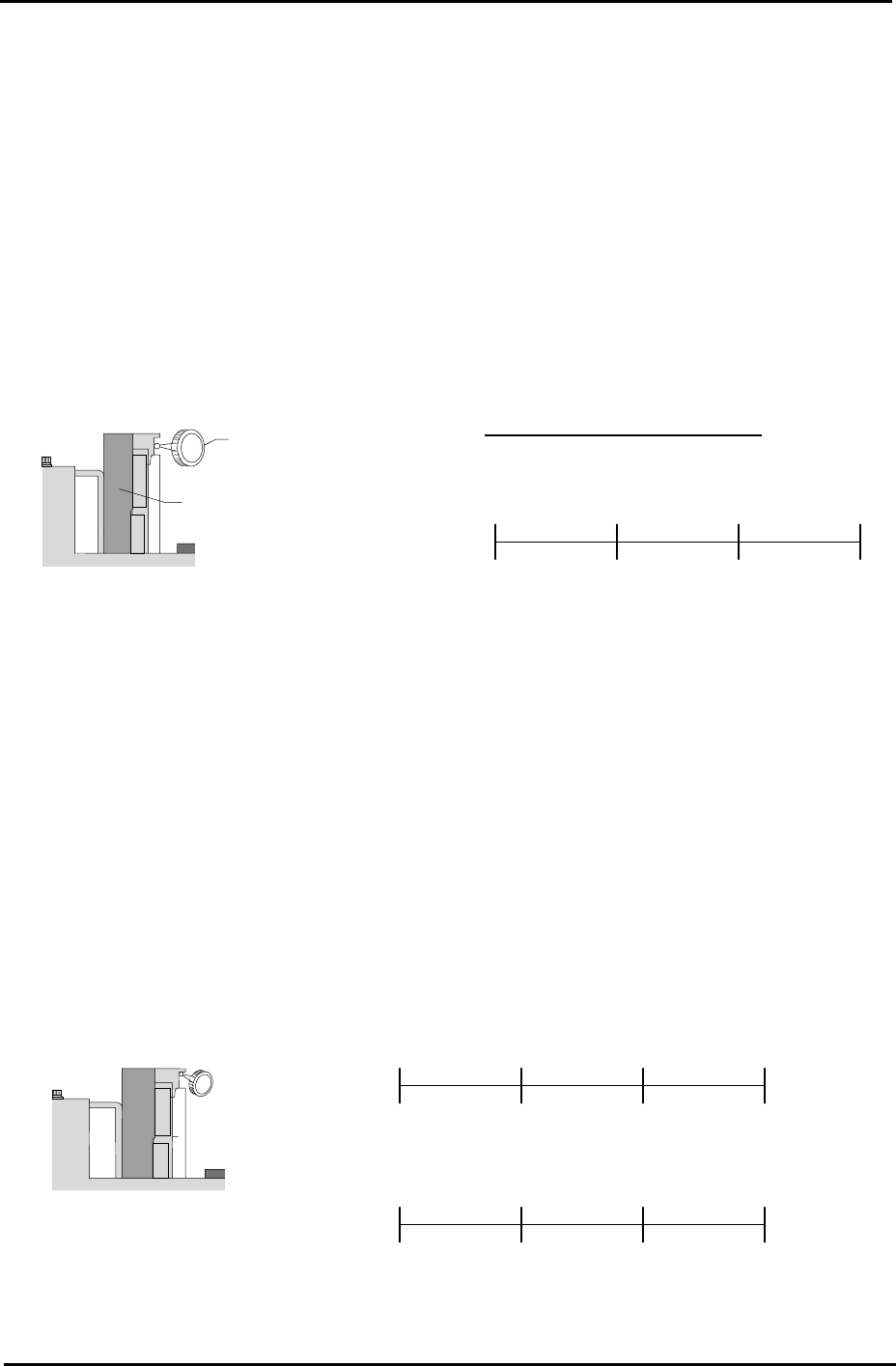
4.3 Conveyor Rails
Rail Parallelism
1. Attach a dial guage to the placing head (an extension bar is necesarry).
2. Set the dial gauge on the fixed conveyor rail.
3. Set the dial gage to “0”. Measure the parallelism of the fixed rail.
4. Record your measurements on the adjustments check sheet:
Dial Gauge
Reference side of the
Conveyor
Tolerance: ±0.05 / 450 mm
(mm) 150 450 300 0
( ) ( ) ( ) (mm) 0
Viewed from the right side
of the machine
Rail Flatness
1. Adjust the conveyor width to 200mm.
2. Set the dial gauge on the underside of the board clamper at the fixed rail side. Measure the
flatness and record the measurements on the adjustment check sheet.
450 300 150 0
(mm)
Reference side of th
conveyor
e
( )
Viewed from the right
side of the machine
0
450 300 150
( ) ( ) ( )
0
( ) ( ) ( ) (mm)
(mm)
(mm)
3. Measure the flatness of the underside of the board clamper at the adjustable rail side.