XP Type II 工程师培训手册 (2.0).pdf.pdf - 第30页
FK-9F98-34 XP T ype II Series T raining T ext for Service Engineers Edition 2.0 XP142E – Chapter 3 S t atic Accu racy Measurement Page 4 of 4 Fuji Machine Mfg. Co., Ltd. Okazaki NOTES: SMT Equipment Quality Assurance Dep…
FK-9F98-34 XP Type II Series Training Text for Service Engineers
Edition 2.0 XP142E – Chapter 3 Static Accuracy Measurement Page 3 of 4
Fuji Machine Mfg. Co., Ltd. Okazaki
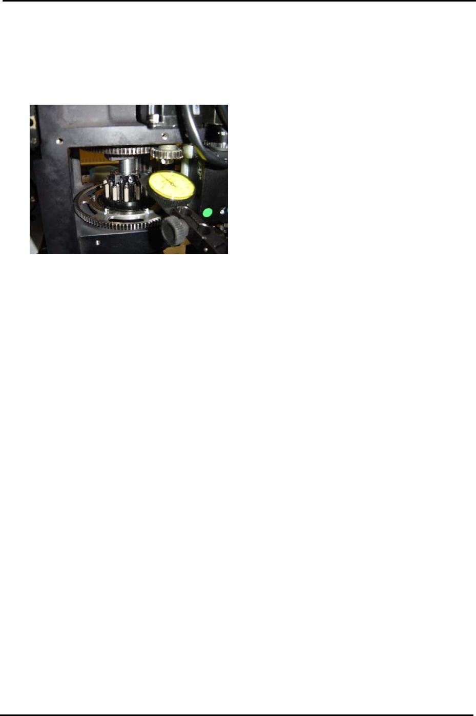
3.3 Piston Deviation
1. Equipment: lever type dial gage (0.01mm).
2. Bring the number 1 nozzle to the front of the machine and set the dial gage on the top of
the nozzle piston as illustrated in the following photo:
3. Using the number 1 nozzle piston height as a reference, move the R axis through one
rotation and measure all the remaining pistons.
4. The height difference between the highest and lowest piston should be within 0.10mm.
If out of tolerance please contact FUJI. Also record which of the 12 pistons is the highest
(this information is necessary for later adjustments).
3.4 Backlash
1. Equipment: lever type dial gage (0.002mm).
2. With the servo ON set the dial gage against the X and Y axes in turn and measure the
backlash.
3. Any backlash should be within 0.01mm.
4. In the case of the Q and R axis gears there should be no backlash.
SMT Equipment Quality Assurance Dept.
3 – 3 CS Section

FK-9F98-34 XP Type II Series Training Text for Service Engineers
Edition 2.0 XP142E – Chapter 3 Static Accuracy Measurement Page 4 of 4
Fuji Machine Mfg. Co., Ltd. Okazaki
NOTES:
SMT Equipment Quality Assurance Dept.
3 – 4 CS Section

C
C
h
h
a
a
p
p
t
t
e
e
r
r
4
4
L
L
o
o
a
a
d
d
e
e
r
r
A
A
d
d
j
j
u
u
s
s
t
t
m
m
e
e
n
n
t
t