XP Type II 工程师培训手册 (2.0).pdf.pdf - 第178页
FK-9F98-34 XP T ype II Series T raining T ext for Service Engineers Edition 2.0 XP242E – Chapter 6 Proper Data Mea surement s Page 23 of 30 3. Select [Maintenance C] – [Proper Data Editor] – [Dispose Position] – [X_Dispo…
FK-9F98-34 XP Type II Series Training Text for Service Engineers
Edition 2.0 XP242E – Chapter 6 Proper Data Measurements Page 22 of 30
6. Select [Maintenance C] – [Nozzle Measurement] – [Size Check Ref. Measurement]
– [START] to carry out the measurement.
7. The results of the [Size Check Ref. Measurement] are saved in the hard drive: /sdo
– System – NzlSizeRange.csv.
6.13 Nozzle Station Operation
1. From the production screen select [Nozzle Editor] and configure the nozzle entries
as described in the following table:
Nozzle Number Nozzle diameter (mm)
1 0.7
2 1.0
3 1.3
4 1.8
5 2.5
6 3.7
7 10
8 15
9 20
2. Arrange the nozzles in the nozzle station so that they match the nozzle editor
configuration.
3. Select [Manual Operation] – [Nozzle operation] – [1] – [Execute] – [START] to pick
up nozzle 1. Check that the placing head picks up the nozzle smoothly and then
select [Place] – [Execute] – [START] to return the nozzle to the nozzle station.
4. Repeat this procedure for all the remaining nozzles.
6.14 Parts Reject Positions
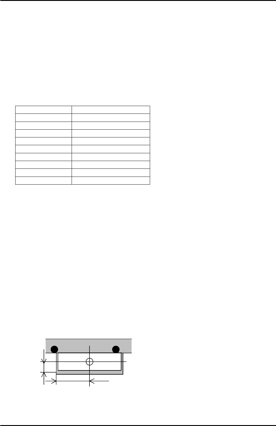
Small Parts Reject Position
1. Select [Maintenance A] – [Jog] – [Fiducial] and display the cross hairs on the
screen.
Small parts reject pos.
12.5mm
35mm
2. Jog the fiducial camera until it is in the centre of the small parts reject box on the
fixed rail. Refer to the diagram above for the dimensions of the box.
Fuji Machine Mfg. Co., Ltd. Okazaki.
SMT Equipment Quality Assurance Dept.
6 – 22 CS Section
FK-9F98-34 XP Type II Series Training Text for Service Engineers
Edition 2.0 XP242E – Chapter 6 Proper Data Measurements Page 23 of 30
3. Select [Maintenance C] – [Proper Data Editor] – [Dispose Position] –
[X_Disposal1/Y_Disposal1] – [Direct Servo Input] to save the current X-axis and Y-
axis positions in proper data.
Large Parts Reject Position
1. Equipment: Nozzle jig (Z95314DEPJ0070)
2. Select [Maintenance A] – [I/O check] – [Y021 NozzleUnhold] – [OFF] and attach the
nozzle jig to the placing head.
3. Select [Maintenance A] – [Jog] – and carefully inch the nozzle jig above the surface
of the reject parts tray.
4. Press the emergency stop button to cut the 200 volt power supply to the servos and
then manually descend the Z-axis until the nozzle jig contacts the surface of the
reject parts tray.
5. Select [Maintenance C] – [Proper data editor] – [Dispose position] – [Z_Disposal 2]
– [Direct servo input] to save the current Z-axis position in proper data.
6. In the case of the reject parts tray the machine software determines the position of
X and Y disposal, so the “X_Disposal 2” and “Y_Disposal 2” entries should be set to
0 by default.
6.15 MFU Pick Up Position
1. Equipment: Nozzle jig (Z9531DEPJ0070). MFU pick up position measurement jig
(Z5531ADPEPJ9010).
2. Select [Manual Operation] – [MFU Clamp] to clamp the MFU to the machine.
3. Mount the MFU pick up position measurement jig at device position 25.
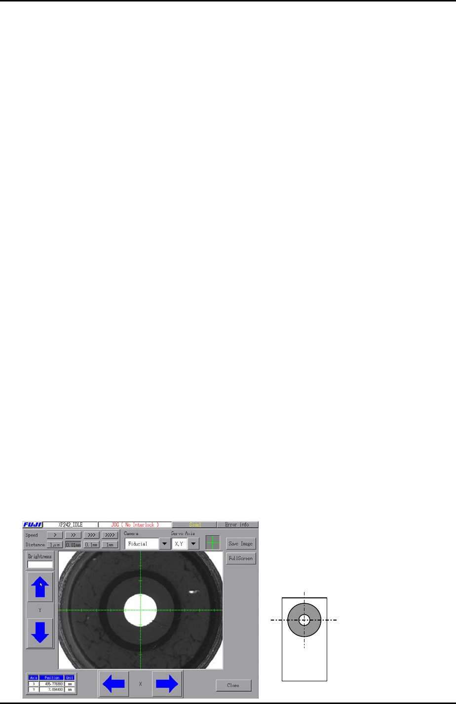
4. Select [Maintenance A] – [Jog] – [Fiducial] and display the cross hairs on the
screen.
5. Inch the X and Y axes until the fiducial camera cross hairs are centered on the XY
pick up position jig mark.
Z5531ADPEPJ9010
Fuji Machine Mfg. Co., Ltd. Okazaki.
SMT Equipment Quality Assurance Dept.
6 – 23 CS Section
FK-9F98-34 XP Type II Series Training Text for Service Engineers
Edition 2.0 XP242E – Chapter 6 Proper Data Measurements Page 24 of 30
6. Select [Maintenance C] – [Proper data editor] – [Machine Origin] –
[X_Stage1Org/Y_Stage1Org] – [Direct servo input] to save the current X and Y
axes positions in proper data.
7. Select [Maintenance A] – [I/O Check] – [Y021 NozzleUnhold] – [OFF] and attach
the nozzle jig to the placing head.
8. Manually bring the nozzle jig above the surface of the MFU pick up position
measurement jig surface and descend the Z-axis until the nozzle jig contacts the
surface.
9. Select [Maintenance C] – [Proper data editor] – [Machine Origin] –
[Z_Stage1surface] – [Direct servo input] to save the current Z-axis position in
proper data.
10. In situations where the MFU pick up position measurement jig is unavailable, a
normal feeder may be used. In this case align the fiducial camera center on the
component in the parts pick up cavity and save the X and Y positions in proper data
by following the procedure above. Set the Z_Stage1surface proper data where a
0.7 diameter nozzle first contacts the component surface.
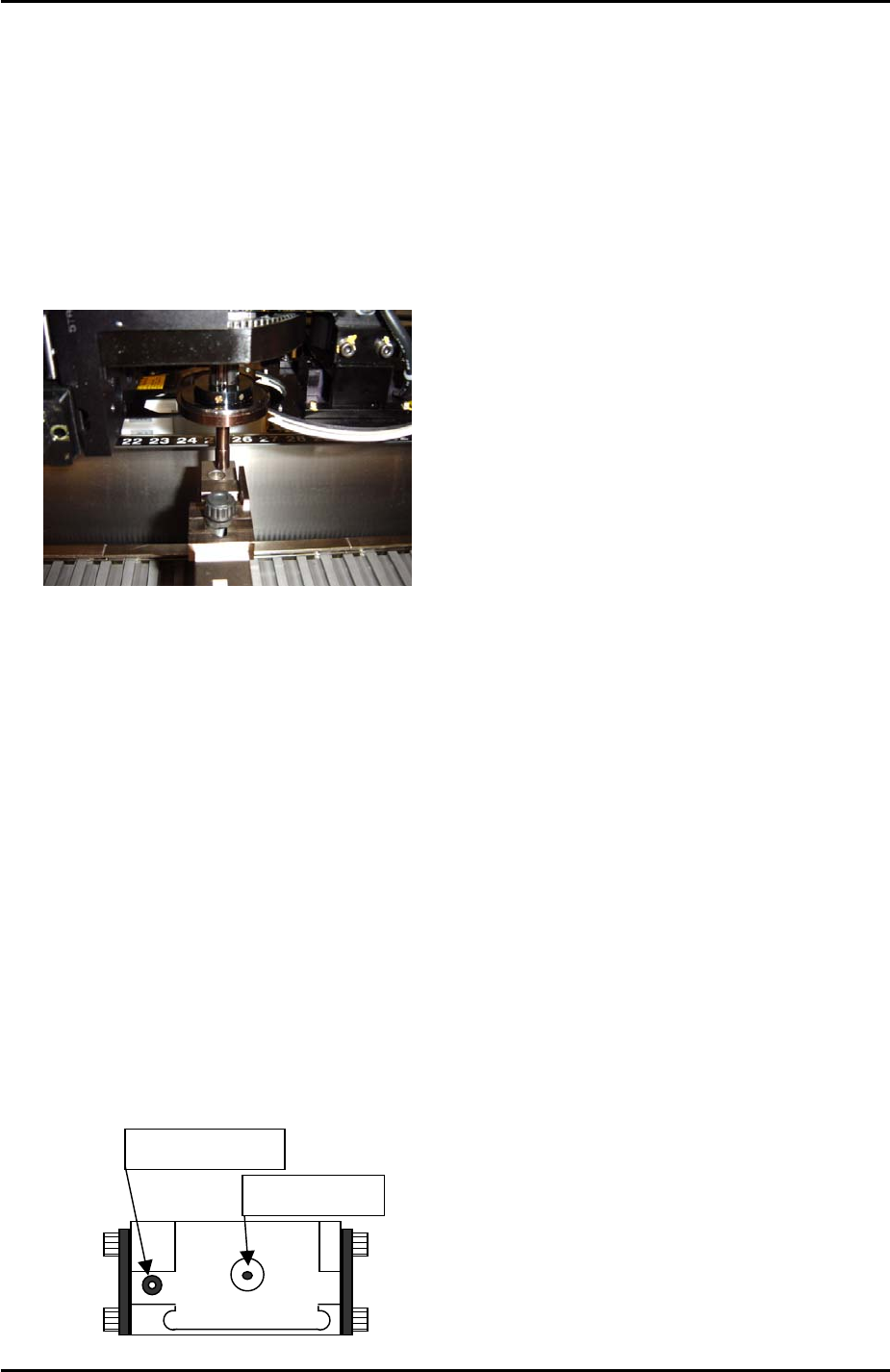
6.16 Glass Gage Position
1. Equipment: Nozzle jig (Z9531DEPJ0070). Glass gage (BVDZ-0140).
2. Select [Maintenance A] – [Jog] – [Fiducial] – and display the cross hairs on the
screen.
3. Inch the X and Y axes until the fiducial camera is centered on the glass gage
station vacuum hole.
Vacuum hole
Fiducial Mark
Fuji Machine Mfg. Co., Ltd. Okazaki.
SMT Equipment Quality Assurance Dept.
6 – 24 CS Section