XP Type II 工程师培训手册 (2.0).pdf.pdf - 第142页
FK-9F98-34 XP T ype II Series T raining T ext for Service Engineers Edition 2.0 XP242E – Chapter 5 Peripheral Adjustm ents Page 4 of 16 5.2 Tape Leaf Check Sensors Double detection type tape leaf sensors Initial Setting …
FK-9F98-34 XP Type II Series Training Text for Service Engineers
Edition 2.0 XP242E – Chapter 5 Peripheral Adjustments Page 3 of 16
X Direction Static Accuracy Check
1. Clamp the reference MFU used in previous steps to side 1.
2. Mount the device jig to device No.2 and set the dial gauge tip to the X-direction.
3. Set the dial to 0. Jog in the Y-direction to detach the dial gage tip from the jig. Record the
present X-axis servo counter. Unclamp the MFU.
4. Clamp another MFU, then mount the device jig to device No.2 and turn the servo ON. Jog
the X axis and check the difference in the X-direction.
X-direction
Tolerance: within 0.050mm
5. Repeat the procedure for any other MFUs
Device I/O Port Check
1. Load the device I/O check feeder on the device table, and use direct I/O (Y040
PartsSendD1) and (Y07F PartsSendD40) to check that all the device position I/0s are
operational.
Note: Use a cloth to wipe any dirt from the MFU connectors.
Fuji Machine Mfg. Co., Ltd. Okazaki.
SMT Equipment Quality Assurance Dept.
5 – 3 CS Section
FK-9F98-34 XP Type II Series Training Text for Service Engineers
Edition 2.0 XP242E – Chapter 5 Peripheral Adjustments Page 4 of 16
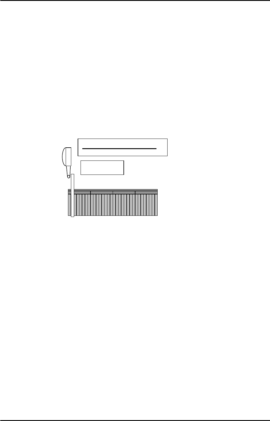
5.2 Tape Leaf Check Sensors
Double detection type tape leaf sensors
Initial Setting
1. Fix the attachment to the fiber sensor using Loctite 222 adhesive.
A
pply Loctite 222 here
Fiber sensor
A
ttachment
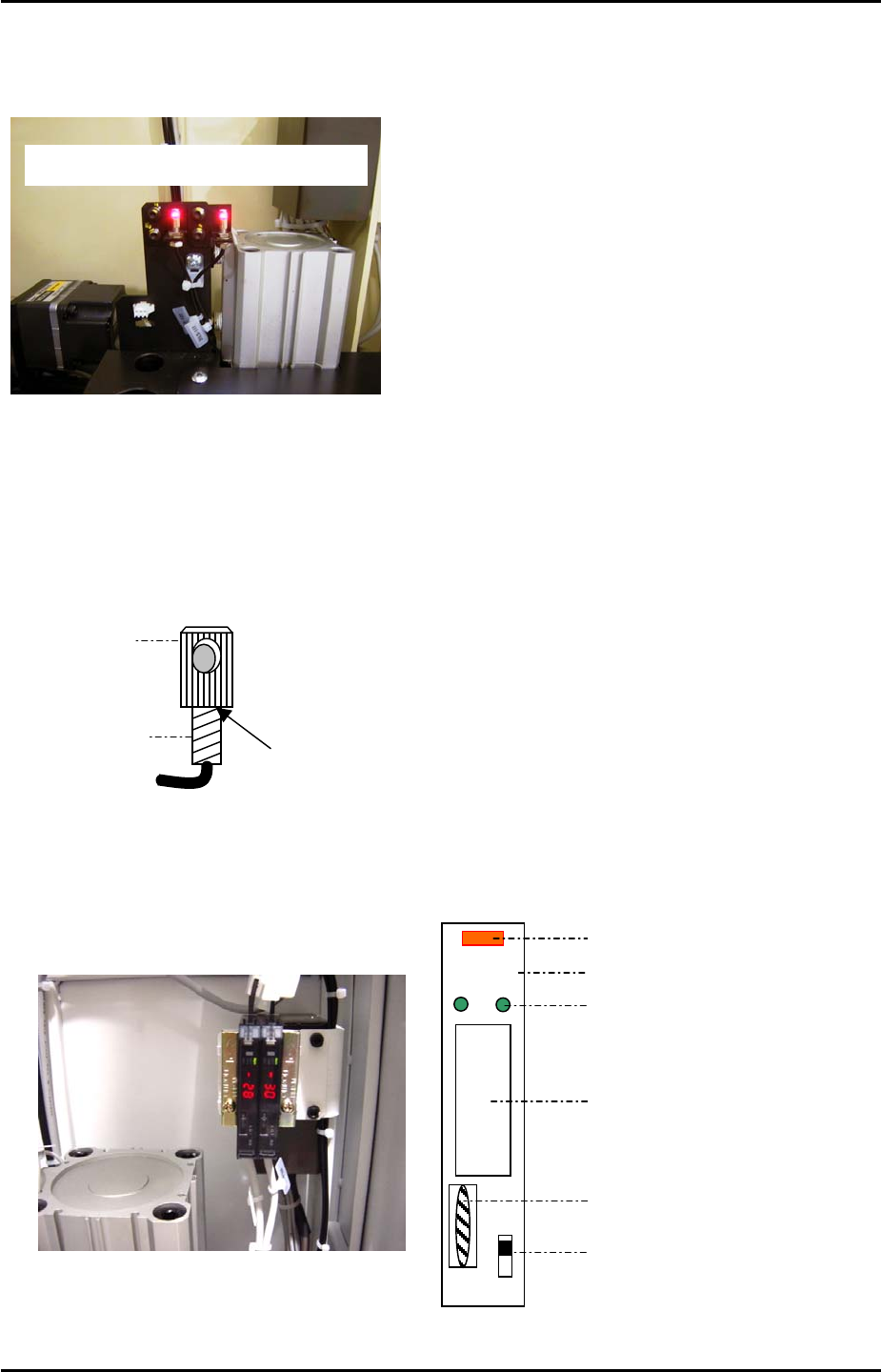
Amplifier Frequency Setting
DO LO
RUN
SET
Digital Display
Operation Light
Mode Lights
Mode Display
Dial Switch
L-ON/D-ON Changeover Switch
Fuji Machine Mfg. Co., Ltd. Okazaki.
SMT Equipment Quality Assurance Dept.
5 – 4 CS Section
FK-9F98-34 XP Type II Series Training Text for Service Engineers
Edition 2.0 XP242E – Chapter 5 Peripheral Adjustments Page 5 of 16
1. Set the L-ON/D-ON changeover switch to L_ON.
2. Press the dial switch once (the RUN light in the Mode Display flashes and “AA” is
displayed on the digital display).
3. Turn the dial switch until SET flashes on the “Mode Display”.
4. Press and hold the dial switch for 3 seconds (SET stops flashing and the Mode Lights
come ON).
5. Turn the dial switch until “– –“ is displayed on the digital display.
6. Press and hold the dial switch for 8 seconds.
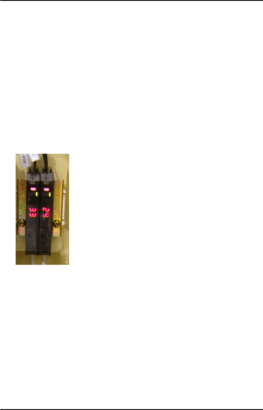
7. Turn the dial to select F1 or F2 depending on which of the two amplifiers are being
adjusted (refer to the photo of the amplifiers below).
Side 1
F2 F1
8. Press the dial switch once so that SET in the Mode Display flashes.
9. Turn the dial until RUN in the mode display flashes.
10. Press the dial switch once (RUN stops flashing and a number 1~100 displays in the
digital display).
11. Repeat the procedure for the other amp.
Fuji Machine Mfg. Co., Ltd. Okazaki.
SMT Equipment Quality Assurance Dept.
5 – 5 CS Section