00197498-03_UM_SiplaceCA-Serie_EN.pdf - 第103页
User Manual SIPLACE CA-Series 2 Operational Safety From software version SC.708.0 Edition 12/20 14 EN -DRAFT 2.10 D isabling the Compressed Air Supply and Discharging the Pressure 103 Fig. 2.10 - 1 Compressed air unit on…
2 Operational Safety User Manual SIPLACE CA-Series
2.10 Disabling the Compressed Air Supply and Discharging the Pressure From software version SC.708.0 Edition 12/2014 EN -DRAFT
102
2.10 Disabling the Compressed Air Supply and Dis-
charging the Pressure
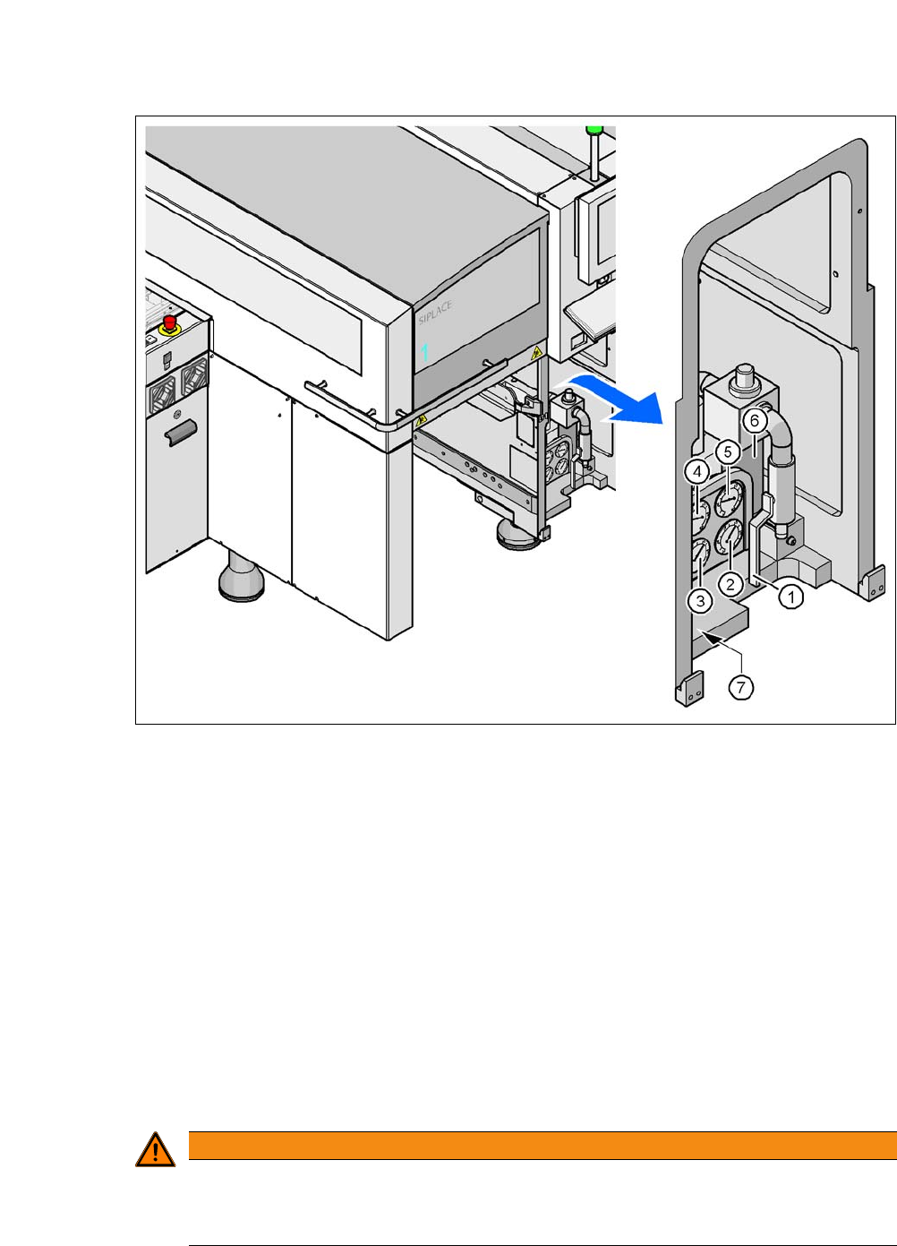
The operating pressure of the machine and SWS is fixed to 0.50 ± 0.025 MPa (5.0 ± 0.25 bar).
The position of the compressed air unit is shown at item 1 in fig. 2.10 - 1
. The supply of com-
pressed air to the machine can be interrupted with the shutoff valve (item 2 in fig. 2.10 - 1
).
The SWS is supplied with compressed air via the machine.
Use the machine key to release the cover lock.
Lift the cover (see fig. 2.10 - 1).
Turn the lever of the shutoff valve (item 1 of fig. 2.10 - 1) from the vertical to the horizontal
position.
Monitor the operating pressure manometer (item 5 in fig. 2.10 - 1). When the machine is
switched on, the pressure discharges to 0 MPa (0 bar) within 1 minute.
2
CAUTION
Interruption to compressed air supply!
When the machine is switched on, do not use the stop valve to interrupt the com-
pressed air supply for more than 30 minutes.
If you need to shut off the pneumatic system for longer in order to carry out preventive
maintenance or servicing work, you must switch the machine off at the main switch
and disconnect it from the power supply.
User Manual SIPLACE CA-Series 2 Operational Safety
From software version SC.708.0 Edition 12/2014 EN -DRAFT 2.10 Disabling the Compressed Air Supply and Discharging the Pressure
103
Fig. 2.10 - 1 Compressed air unit on the machine
(1) Shutoff valve
(2) Manometer for the machine component supply pressure
Target pressure: 0.48 ± 0.025 MPa, 4.8 ± 0.25 bar (display range 0 - 0.6 MPa, 0 - 6 bar)
(3) Manometer for gantry distributor supply pressure
Target pressure: 0.46 ± 0.01 MPa, 4.6 ± 0.1 bar (display range 0 - 0.6 MPa, 0 - 6 bar)
(4) Manometer for the bulk case feeder modules supply pressure
Target pressure: 0.25 ± 0.05 MPa, 2.5 ± 0.5 bar (display range: 0 - 0.6 MPa, 0 - 6 bar)
(5) Manometer for inlet pressure
Target pressure: 0.5 - 1.0 MPa, 5 - 10 bar (display range: 0 - 1.0 MPa, 0 - 10 bar)
(6) Compressed air filter
(7) Hexagon socket-head screw for fixing the pneumatic unit
2
WARNING
Risk of injuries!
Risk of injuries from pressurized compressed air lines.
NEVER detach compressed air lines while they are still pressurized.
2 Operational Safety User Manual SIPLACE CA-Series
2.10 Disabling the Compressed Air Supply and Discharging the Pressure From software version SC.708.0 Edition 12/2014 EN -DRAFT
104
2
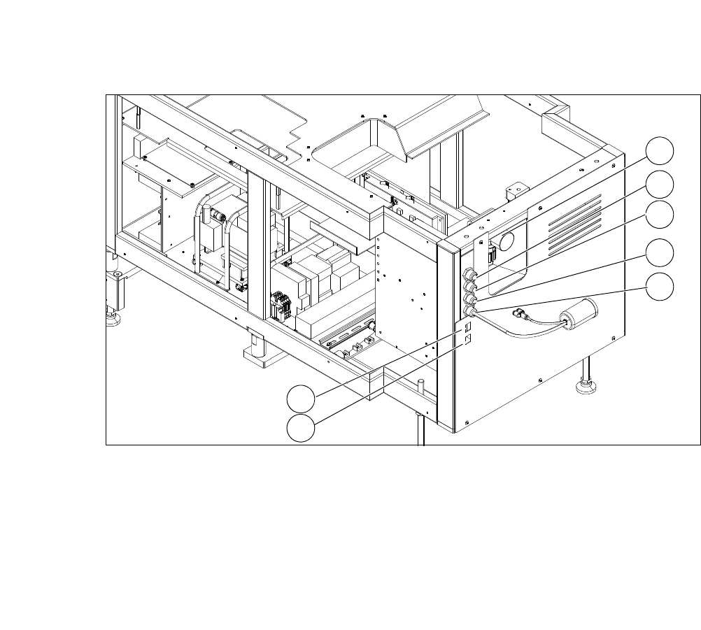
Fig. 2.10 - 2 Electrical and pneumatic connection on the SWS
2
(1) Manometer for compressed air supply (2) Voltage supply
(3) Communication with SIPLACE machine (4) CAN bus
(5) Compressed air connection (modified
adapter dummy connector [03011592-01])
(6) LAN1
(7) LAN2
2
1
3
4
5
6
7