00197498-03_UM_SiplaceCA-Serie_EN.pdf - 第140页
3 Technical Data User Manual SIPLACE CA-Series 3.5 Line Concept From software version SC.708.0 Edition 12/2014 EN -DRAFT 140 3.5 Line Concept 3.5.1 Description 3 The SIPLACE concept is distinguished by its flex ibility ,…
User Manual SIPLACE CA-Series 3 Technical Data
From software version SC.708.0 Edition 12/2014 EN -DRAFT 3.4 Dimensions and Weight of the SIPLACE CA
139
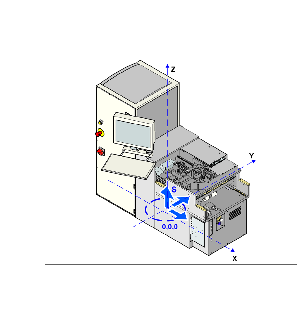
3.4.8 Center of Gravity for SWS
3
Fig. 3.4 - 10 Coordinate system for SWS center of gravity
3
Center of gravity coordinates:
SWS X coordinate
Y coordinate
0 mm
650 mm
3 Technical Data User Manual SIPLACE CA-Series
3.5 Line Concept From software version SC.708.0 Edition 12/2014 EN -DRAFT
140
3.5 Line Concept
3.5.1 Description
3
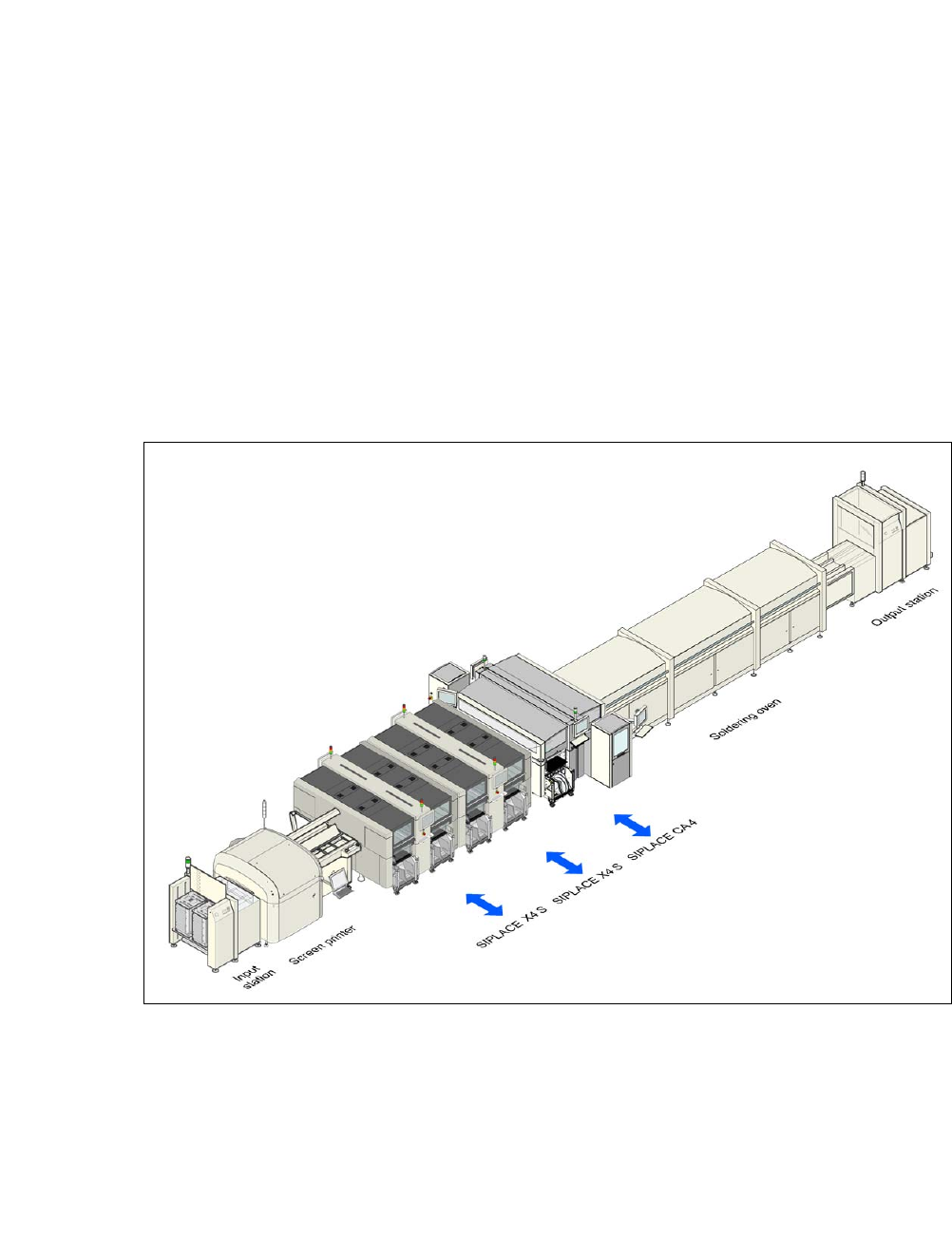
The SIPLACE concept is distinguished by its flexibility, modularity, compact design and high per-
formance. Operated together with the SIPLACE X-Series, the SIPLACE CA machine allows you
to individually configure your production line with both identical and differing modules. If the pro-
duction requirements change, the individual placement machines are so compact and can be
combined with such flexibility that they can be recombined quickly and easily.
3
Fig. 3.5 - 1 Sample line concept
3
The SIPLACE family has the optimum placement system for each individual performance require-
ment.
SIPLACE CA-Series machines can place bare dies directly from the wafer, by using the flip chip
or die attach process, and can also place the entire SMD spectrum covered by the SIPLACE X
machines. The SIPLACE CA therefore marks the starting point of an innovative new placement
technology in the SIPLACE family.

User Manual SIPLACE CA-Series 3 Technical Data
From software version SC.708.0 Edition 12/2014 EN -DRAFT 3.5 Line Concept
141
The machine is equipped with both SIPLACE wafer systems and with changeover tables and can
therefore produce the entire product with SMDs and bare dies, in one production cycle.
The SIPLACE CA even demonstrates a higher throughput performance than previous placement
systems for products which are only placed with bare dies.
Since this new concept combines at least two production lines to form a single lines (SMD and
bare die placement), the investment costs and cost of ownership can be reduced significantly.
Over the medium term, our customers will be able to convert their production lines from IC pack-
ages to bare die placement, thereby improving lead times, product costs and product dimensions.