00197498-03_UM_SiplaceCA-Serie_EN.pdf - 第276页
5 Setting up and Commissioning User Manual SIPLACE CA-Series 5.4 Infrastructure at the Installation Location From software version SC.708.0 Edition 12/2014 EN -DRAFT 276 5.4.4.4 Connecting the Power Supply Cable 5 Fig. 5…
User Manual SIPLACE CA-Series 5 Setting up and Commissioning
From software version SC.708.0 Edition 12/2014 EN -DRAFT 5.4 Infrastructure at the Installation Location
275
5
5
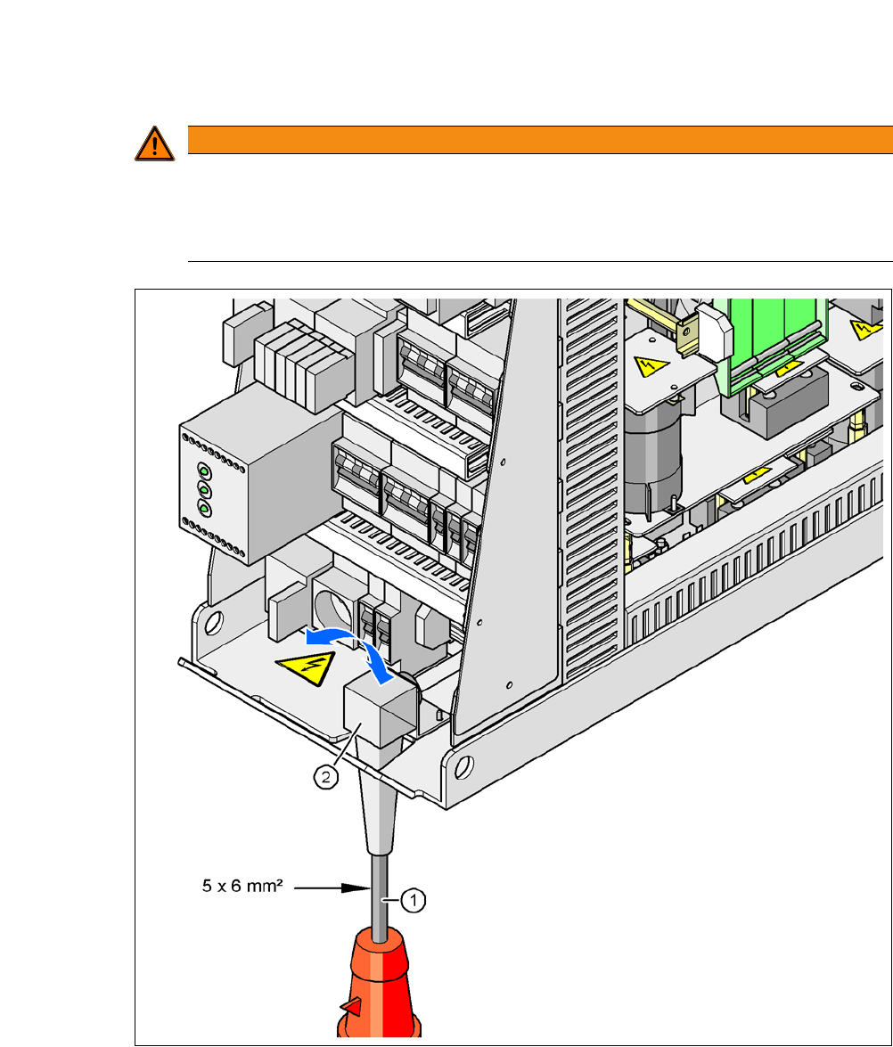
Fig. 5.4 - 3 Cross-section of the main power cable
(1) Power supply cable
(2) Angled cable gland
WARNING
Clear marking of electrical leads!
The electrical leads to each individual machine and to the installed options (e.g. (SWS,
Productivity Lift) must be clearly marked and easy to assign without confusion.
The regulations of the country in which the machine is operated apply.
5 Setting up and Commissioning User Manual SIPLACE CA-Series
5.4 Infrastructure at the Installation Location From software version SC.708.0 Edition 12/2014 EN -DRAFT
276
5.4.4.4 Connecting the Power Supply Cable
5
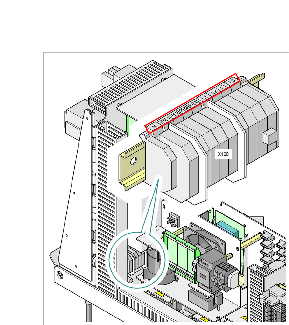
Fig. 5.4 - 4 Terminal panel for connecting the power cable
(L1) Three-phase A.C. current
(L2) Three-phase A.C. current
(L3) Three-phase A.C. current
(N) Neutral wire
(PE) protective earth wires PE1, PE2, PE3, PE4
(X100) Terminal panel

User Manual SIPLACE CA-Series 5 Setting up and Commissioning
From software version SC.708.0 Edition 12/2014 EN -DRAFT 5.4 Infrastructure at the Installation Location
277
Crimp a ferrule onto each end of the wire.
Loosen the nut on the angled cable gland (item 2 in fig. 5.4 - 3).
Fold up the angled cable gland.
Run the power supply cable through the angled cable gland and to the terminal panel X100
(see X100 in fig. 5.4 - 4
).
Connect the cable to the terminal and ensure that it has a sufficient bending radius. The wires
must not be kinked.
Close the angled cable gland (item 2 in fig. 5.4 - 3) and hand-tighten the nut.
5.4.4.5 Checking the Inrush Current Limitation Jumpers
The inrush current limitation must be configured in relation to the supply voltage. This is achieved
with the help of plug-in bridges on the inrush current limitation board (item 1 in fig. 5.4 - 5
).