00197498-03_UM_SiplaceCA-Serie_EN.pdf - 第109页
User Manual SIPLACE CA-Series 2 Operational Safety From software version SC.708.0 Edition 12/20 14 EN -DRA FT 2.11 Energy State After Switching off Main Switch 109 2.1 1.1.1 Machine Switched off at the Main Switc h, But …
2 Operational Safety User Manual SIPLACE CA-Series
2.11 Energy State After Switching off Main Switch From software version SC.708.0 Edition 12/2014 EN -DRAFT
108
2
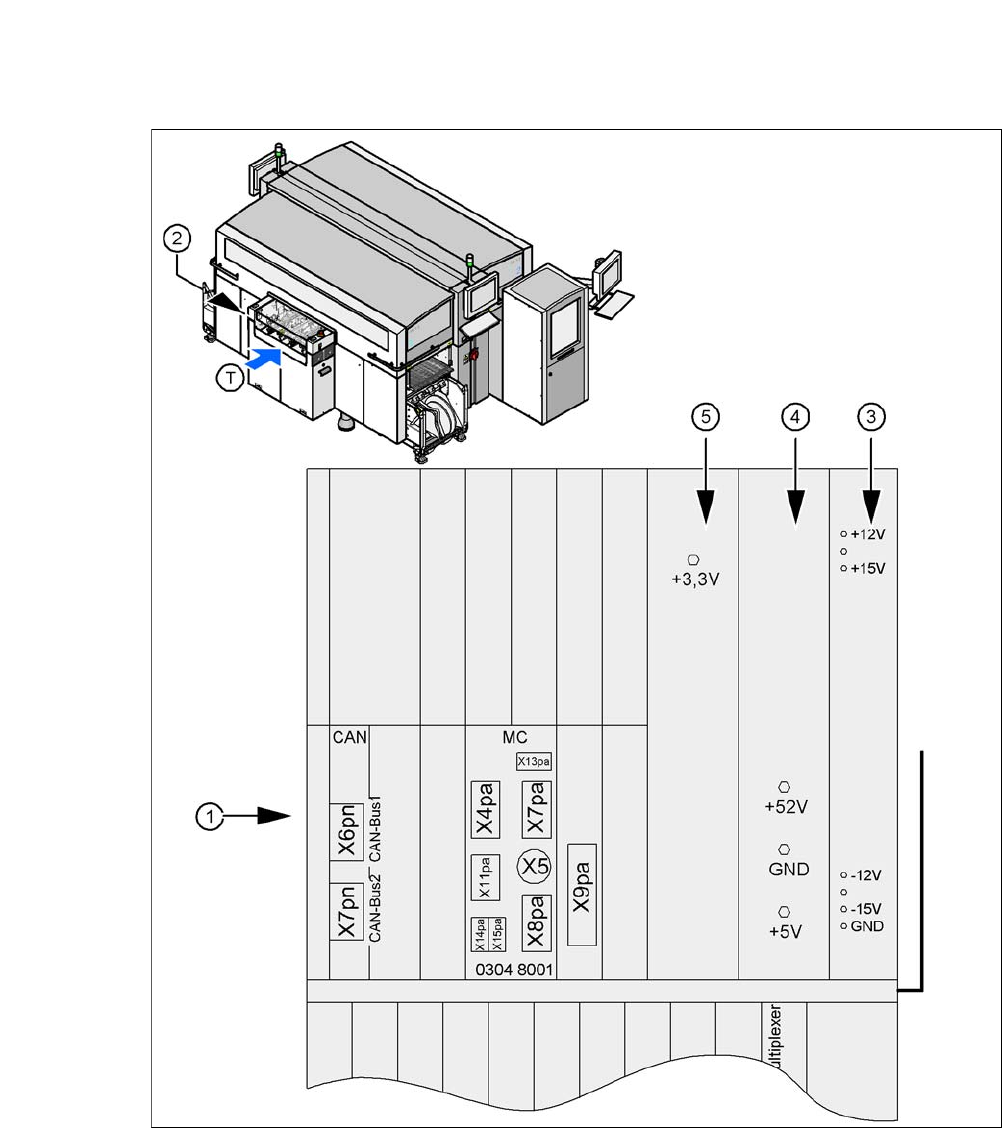
Fig. 2.11 - 3 Position of computer unit
(1) Computer unit (top part)
(2) Position of computer unit
(3) Power supply unit ± 12 V-/± 15 V-
(4) Power supply unit + 5 V-/+ 52 V-
(5) Power supply unit + 3.3V-
(T) Direction of PCB transport
User Manual SIPLACE CA-Series 2 Operational Safety
From software version SC.708.0 Edition 12/2014 EN -DRAFT 2.11 Energy State After Switching off Main Switch
109
2.11.1.1 Machine Switched off at the Main Switch, But Still Connected
2
DANGER
Lethal voltages!
Incorrect handling of the machine can therefore result in death or severe injury or consid-
erable damage to equipment.
The following components still carry potentially lethal voltages even if the main power
switch is switched off:
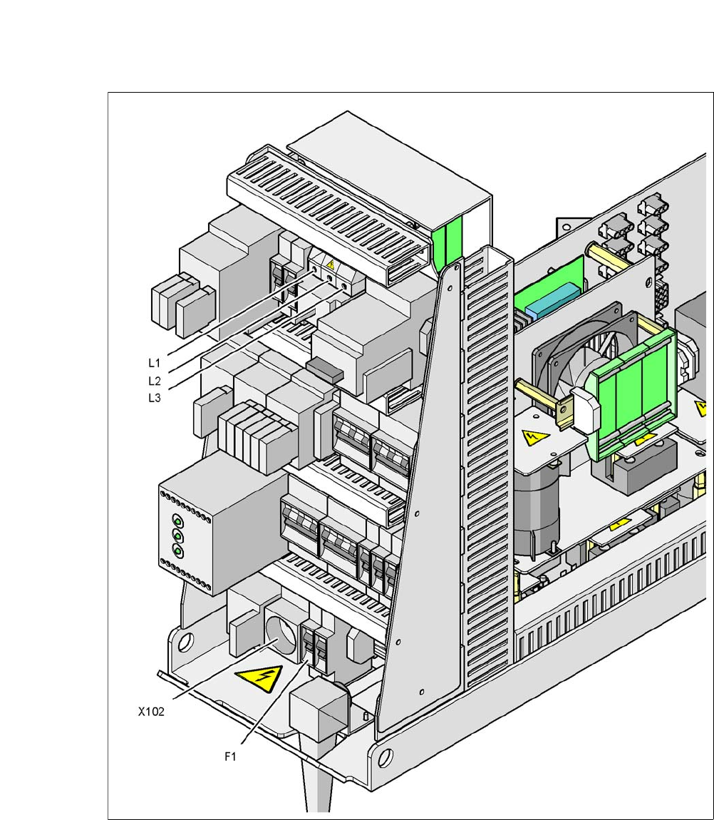
– Cable connection terminals L1, L2 and L3 of the main switch Q1 (see fig. 2.11 - 4
)
– Service socket X102 (see fig. 2.11 - 4
)
– F1 automatic circuit breaker for the service socket (see fig. 2.11 - 4
)
– Mains filter Z1 (see fig. 2.11 - 5
)
– Discharge inductor L20 with fuses F21, F22 and F23 (see fig. 2.11 - 5
)
– Terminal panel X100 for connecting the mains power supply cable (see fig. 2.11 - 5
)
– The color of all individual wires, which still carry potentially lethal voltages even if the
main power switch is switched off, is brown.
– Axis unit.
Always follow the applicable accident prevention and DIN regulations (particularly EN
60204, part 1 or IEC 60204, part 1) and the applicable regulations in your own coun-
try.
The safety door to the power supply must ONLY be opened by appropriately qualified
and trained personnel.
2 Operational Safety User Manual SIPLACE CA-Series
2.11 Energy State After Switching off Main Switch From software version SC.708.0 Edition 12/2014 EN -DRAFT
110
2
Fig. 2.11 - 4 Power supply unit, view from front
Q1 Main switch
X102 Service socket
F1 Fuse for service socket