00197498-03_UM_SiplaceCA-Serie_EN.pdf - 第303页
User Manual SIPLACE CA-Series 5 Setting up and Commissioning From software version SC.708.0 Edition 12/20 14 EN -DRAFT 5.5 Setting Up the Placement Machine 303 5.5.10 Fitting the Extension Kit to the PCB Input Side 5.5.1…
5 Setting up and Commissioning User Manual SIPLACE CA-Series
5.5 Setting Up the Placement Machine From software version SC.708.0 Edition 12/2014 EN -DRAFT
302
Dismantle the cable covers (item 3 and 5 in fig. 5.5 - 13) on the input conveyor (item 1 in fig.
5.5 - 13
).
Place the side (item 1 in fig. 5.5 - 13) carefully against the side of the processing conveyor
(item 2 in fig. 5.5 - 13
).
5
Fasten each side with 4 fillister head screws M6x16 and the corresponding discs (item 7 in
fig. 5.5 - 13
).
Connect the power cable to the light barriers and drive motors.
Fasten the cable covers (item 3 and 5 in fig. 5.5 - 13).
Insert the hexagonal shaft (item 9 in fig. 5.5 - 13) into the drive unit (item 10 in fig. 5.5 - 13).
Make sure that the hexagonal shaft guidance (item 8 in fig. 5.5 - 13) always points to the con-
veyor side to which the drive unit (item 10 in fig. 5.5 - 13
) is fixed.
CAUTION
Be careful not to cut through any of the light barrier or drive motor cables.
User Manual SIPLACE CA-Series 5 Setting up and Commissioning
From software version SC.708.0 Edition 12/2014 EN -DRAFT 5.5 Setting Up the Placement Machine
303
5.5.10 Fitting the Extension Kit to the PCB Input Side
5.5.10.1 Tools
– Allen keys, DIN 911, set
– Machine key
5.5.10.2 Assembly
5
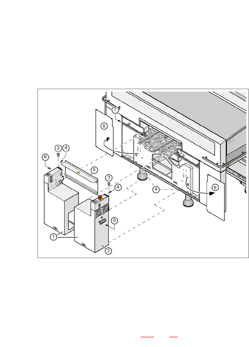
Fig. 5.5 - 14 Fitting the extension kit to the PCB input side
(1) Extension kit, dismantled
(2) Door
(3) Fillister head screw DIN 912, M6x16 and washer
(4) Grounding connection
(5) Transport cover
(6) Side plate, dismantled
(7) Insert rail
(8) Computer unit or box PB unit (see section 5.5.11
, page 308)
(9) Axis unit (CA4)
5 Setting up and Commissioning User Manual SIPLACE CA-Series
5.5 Setting Up the Placement Machine From software version SC.708.0 Edition 12/2014 EN -DRAFT
304
Remove both side plates (item 6 in fig. 5.5 - 14).
5
Detach the ground cable from the side plate.
Remove both doors (item 2 in fig. 5.5 - 14) from the extension kit (item 1).
5
Place the computer unit/box PC unit (item 8 in fig. 5.5 - 14) and the axis unit (item 9 in fig. 5.5
- 14) down to one side of the placement machine, leaving enough room to fit the extension kit
(item 1 in fig. 5.5 - 14
).
Make sure that the connection cable to the computer unit / Box PC unit and the axis unit is
not under tension.
Lift one half of the extension kit (item 1 in fig. 5.5 - 14) up to the machine frame and position
these so that the assembly bracket lies on the unit rail (item 7 in fig. 5.5 - 14
).
5
Fasten this half of the extension kit with 2 fillister head screws M6x16 and the corresponding
discs (item 3 in fig. 5.5 - 14
).
Before assembling the second half of the extension kit, fit the conveyor covers (item 5 in fig.
5.5 - 14
). The procedure is as follows:
CAUTION
Risk of injuries!
When you unscrew the three lower screws, the side panel could fall down and cause in-
juries.
Loosen the three lower screws but do not fully unscrew them for now.
PLEASE NOTE
Avoiding damage
To avoid damage, we recommend that a second person helps to assemble the extension
kit.
CAUTION
Risk of collisions!
Half of the extension kit could collide with the hexagonal shaft of the PCB conveyor. The
hexagonal shaft could be bent.
Make sure that this half of the extension kit does not collide with the hexagonal shaft
of the PCB conveyor and thus bend the shaft.