00197498-03_UM_SiplaceCA-Serie_EN.pdf - 第293页
User Manual SIPLACE CA-Series 5 Setting up and Commissioning From software version SC.708.0 Edition 12/20 14 EN -DRAFT 5.5 Setting Up the Placement Machine 293 5 Remove bot h side plates (item 6 in f ig. 5.5 - 8 ). 5 …
5 Setting up and Commissioning User Manual SIPLACE CA-Series
5.5 Setting Up the Placement Machine From software version SC.708.0 Edition 12/2014 EN -DRAFT
292
5.5.7.2 Assembly
5
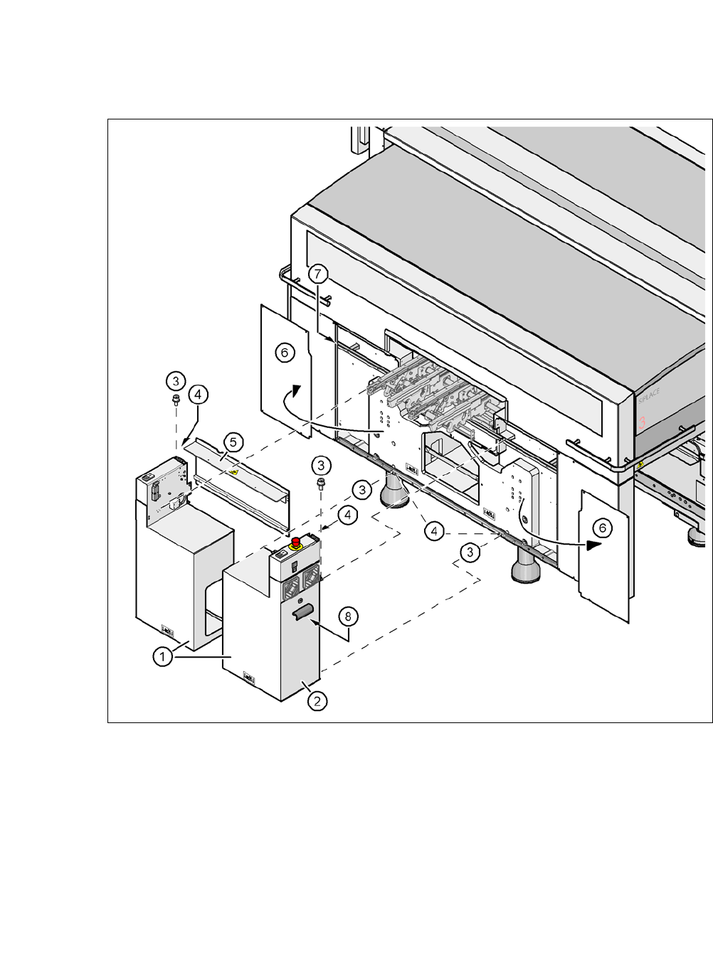
Fig. 5.5 - 8 Fitting the extension kit to the PCB output side
(1) Extension kit
(2) Door
(3) Fillister head screw DIN 912, M6x16 and washer
(4) Grounding connection
(5) Transport cover
(6) Side plate, dismantled
(7) Insert rail
(8) Axis unit gantries 2 and 3 (CA4)
User Manual SIPLACE CA-Series 5 Setting up and Commissioning
From software version SC.708.0 Edition 12/2014 EN -DRAFT 5.5 Setting Up the Placement Machine
293
5
Remove both side plates (item 6 in fig. 5.5 - 8).
5
Detach the ground cable from the side plate.
Remove both doors (item 2 in fig. 5.5 - 8) from the extension kit (item 1).
5
Place the axis unit (item 8 in fig. 5.5 - 8) down to one side of the placement machine, leaving
enough room to fit the extension kit (item 1 in fig. 5.5 - 8
).
Make sure that the connecting cables to the axis unit are not too tight.
Lift one half of the extension kit (item 1 in fig. 5.5 - 8) up to the machine frame and position
these so that the assembly bracket lies on the assembly bar (item 7 in fig. 5.5 - 8
).
5
Fasten this half of the extension kit with 2 fillister head screws M6x16 and the corresponding
washers (item 3 in fig. 5.5 - 8
).
Before assembling the second half of the extension kit, fit the conveyor covers (item 5 in fig.
5.5 - 8
). The procedure is as follows:
CAUTION
Risk of injuries!
When you unscrew the three lower screws, the side panel could fall down and cause in-
juries.
Loosen the three lower screws but do not fully unscrew them for now.
PLEASE NOTE
Avoiding damage
To avoid damage, we recommend that a second person helps to assemble the extension
kit.
CAUTION
Risk of collisions!
Half of the extension kit could collide with the hexagonal shaft of the PCB conveyor. The hexagonal
shaft could be bent.
Make sure that this half of the extension kit does not collide with the hexagonal shaft of the PCB
conveyor and thus bend the shaft.
5 Setting up and Commissioning User Manual SIPLACE CA-Series
5.5 Setting Up the Placement Machine From software version SC.708.0 Edition 12/2014 EN -DRAFT
294
5
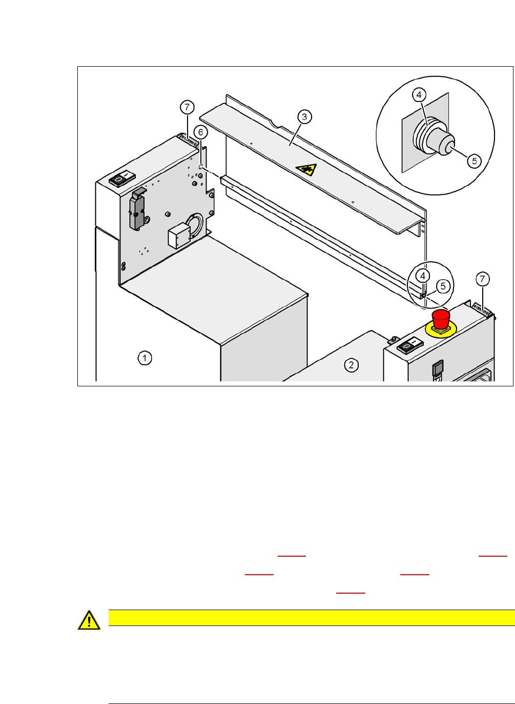
Fig. 5.5 - 9 Fitting the conveyor cover and the second half of the extension kit
(1) Half of the extension kit already fitted
(2) Second half of the extension kit to be fitted
(3) Transport cover
(4) Insert 3 white plastic washers on both sides
(5) Mandrel of the conveyor cover
(6) Hole
(7) Protective cover switch
Insert 3 white plastic discs (item 4 in fig. 5.5 - 9) onto the two mandrels (items 5 in fig. 5.5 - 9).
Insert the mandrel (item 5 in fig. 5.5 - 9) into the hole (item 6 in fig. 5.5 - 9).
Lift the second half of the extension kit (item 2 in fig. 5.5 - 9) up to the machine frame.
5
CAUTION
Risk of collisions!
Half of the extension kit could collide with the hexagonal shaft of the PCB conveyor. The
hexagonal shaft could be bent.
Make sure that this half of the extension kit does not collide with the hexagonal shaft
of the PCB conveyor and thus bend the shaft.