00197498-03_UM_SiplaceCA-Serie_EN.pdf - 第388页
6 Working with the Machine User Manual SIPLACE CA-Series 6.14 Docking/Undocking the Component Trolley From softw are version SC.708.0 Edition 12/2014 EN -DRAFT 388 The safety concept for the component trolley changeover …
User Manual SIPLACE CA-Series 6 Working with the Machine
From software version SC.708.0 Edition 12/2014 EN -DRAFT 6.14 Docking/Undocking the Component Trolley
387
6.14 Docking/Undocking the Component Trolley
6.14.1 Safety instructions for Docking and Undocking Component Trolleys
6
6
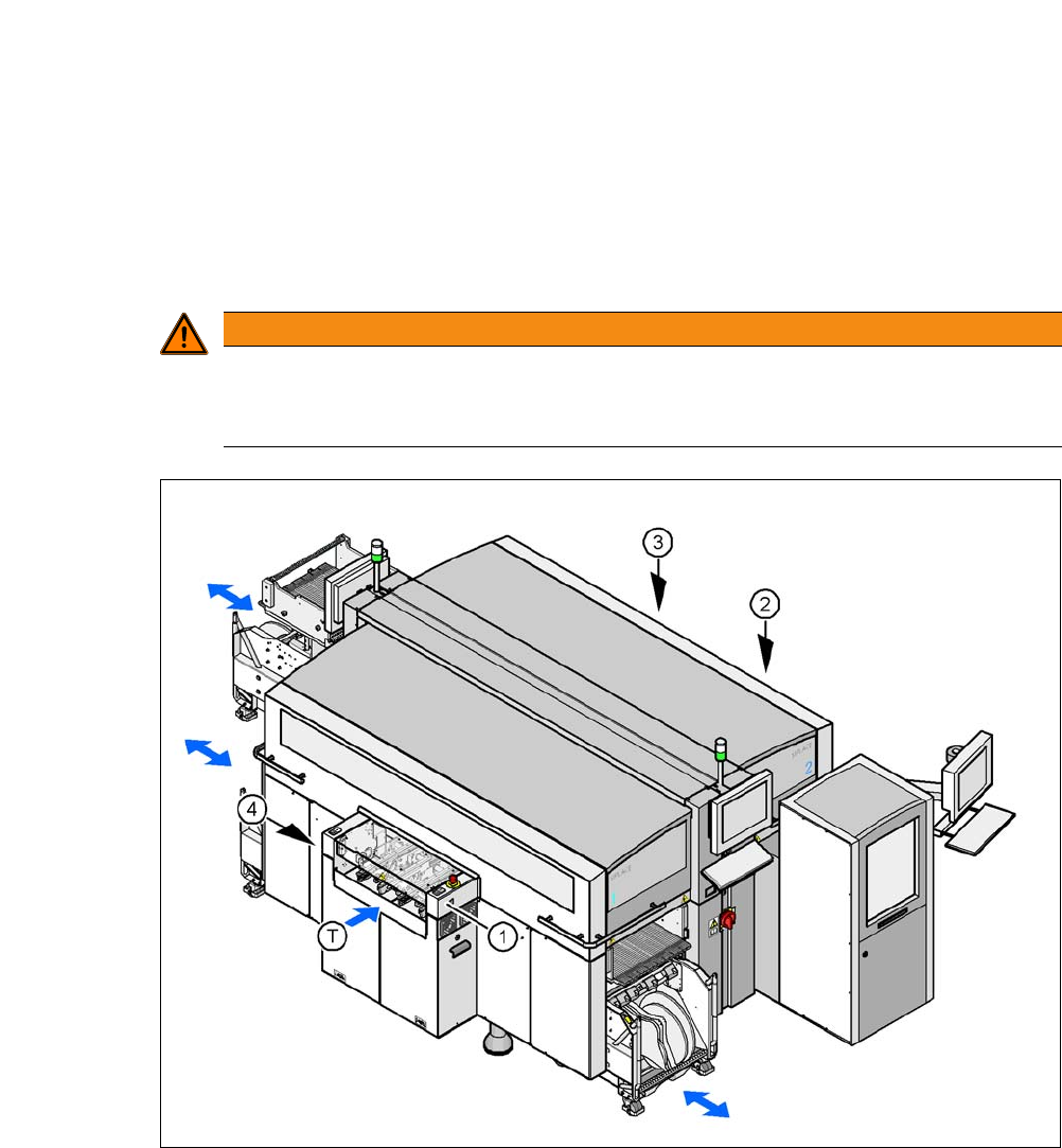
Fig. 6.14 - 1 Safety instructions for docking the component trolley in or out
(1) Button for docking the component trolley in or out, location 1
(2) Button for docking and undocking the component trolley, location 2 (without function here, as
the location is occupied with an SWS)
(3) Button for docking the component trolley in or out, location 3
(4) Button for docking the component trolley in or out, location 4
(T) Direction of PCB transport
WARNING
DANGER OF CRUSHING!
Risk of crushing limbs when docking and undocking the component trolley.
Always dock/undock the component trolley alone.
6 Working with the Machine User Manual SIPLACE CA-Series
6.14 Docking/Undocking the Component Trolley From software version SC.708.0 Edition 12/2014 EN -DRAFT
388
The safety concept for the component trolley changeover prescribes that the user presses a but-
ton (item 1, 2, 3 or 4 in fig. 6.14 - 1
) on the input or output side of the machine, in order to dock or
undock the component trolley. This ensures that the operator is always standing to the side of the
placement machine. In addition, the component trolley can only be docked in if the protective cov-
ers are closed.
6.14.2 Undocking the Component Trolley
Click on the STOP PROCESSING PCB icon in the MAIN VIEW menu.
The PCB in progress will be completed. The icons of the SINGLE FUNCTIONS menu will
then be activated. 6
Click on the desired icon SINGLE FUNCTIONS GANTRY.
Select GANTRY FUNCTIONS.
From this menu, click on the GO TO SET-UP POSITION button.
All the placement heads will move across the PCB conveyor to prevent them being damaged
when the component trolley is changed. 6
Press the appropriate button on the input or output side of the machine (item 1, 2, 3 or 4 in
fig. 6.14 - 1
) until the component trolley has been undocked.
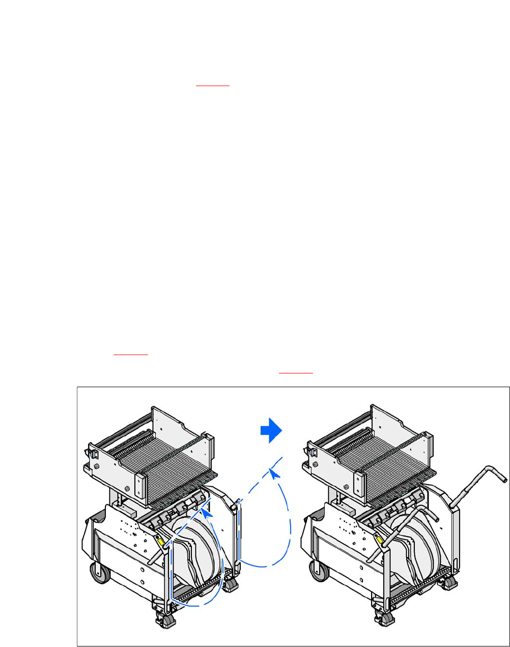
Swivel the two handles up (item 1 in fig. 6.14 - 2).
6
Fig. 6.14 - 2 Component trolley - swivel handles up to push
6
With both hands on the handles, pull the component trolley out of the machine.
User Manual SIPLACE CA-Series 6 Working with the Machine
From software version SC.708.0 Edition 12/2014 EN -DRAFT 6.14 Docking/Undocking the Component Trolley
389
6
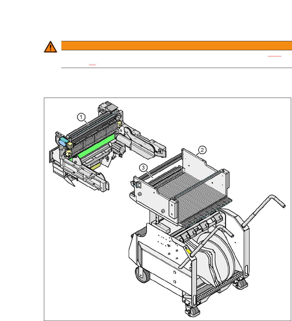
6.14.3 Docking the X-Series Component Trolley
6
Fig. 6.14 - 3 Component trolley and COT insert, SIPLACE X-Series
(1) Component trolley docking unit, SIPLACE X-Series
(2) Component trolley, SIPLACE X-Series
(3) Locking latches
WARNING
Observe the safety instructions for moving the component trolley in section 2.6.7,
page 76
.