00197498-03_UM_SiplaceCA-Serie_EN.pdf - 第288页
5 Setting up and Commissioning User Manual SIPLACE CA-Series 5.5 Setting Up the Placement Machine From software version SC.708.0 Edition 12/2014 EN -DR AFT 288 Insert the correct machine foot for the require d PCB conv…
User Manual SIPLACE CA-Series 5 Setting up and Commissioning
From software version SC.708.0 Edition 12/2014 EN -DRAFT 5.5 Setting Up the Placement Machine
287
5.5.4.2 Presetting the Height of the Outer Machine Feet
5
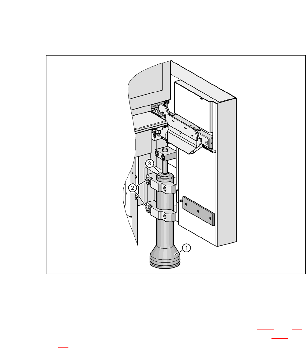
Fig. 5.5 - 6 Presetting the height of the outer machine feet
(1) Machine feet, - 2 versions
(2) Hexagon socket-head screw M24x90
(3) M24x2x120 adjusting screw
Carefully loosen both hexagon socket-head screws M24x90 (item 2 in fig. 5.5 - 6, page 287)
with the screwdriver bit (size 19 mm) and let the outer machine foot (item 1 in fig. 5.5 - 6
, page
287
) slowly slide down as far as the end stop.
5 Setting up and Commissioning User Manual SIPLACE CA-Series
5.5 Setting Up the Placement Machine From software version SC.708.0 Edition 12/2014 EN -DRAFT
288
Insert the correct machine foot for the required PCB conveyor height.
The outer machine feet are available in two versions: 5
– Outer machine foot for PCB conveyor heights 900, 930 and 950 mm, Length 439 mm
[03000890-02] (item 2 in fig. 5.5 - 3
, page 284)
Perform this presetting for each of the outer machine feet.
The distance between the machine foot underside and the lower edge of the machine frame
should be as follows:
Adjust the setting screw M24x2x120 (item 3 in fig. 5.5 - 6, page 287) with the fork wrench SW
36, so that you achieve the distance values for the relevant conveyor height, as specified in
the table above.
Carefully lower the placement machine with the fork-lift truck, until the machine feet touch the
floor evenly. There should always be a second person present to ensure that the machine re-
mains stable while it is being lowered. You may need to loosen the outer machine feet clamp
slightly.
Continue to carefully lower the placement machine, until the outer machine feet touch the
height adjustment setting screws M24x2x120 (item 3 in fig. 5.5 - 6
, page 287).
Make sure that the middle machine feet (see item 2 in fig. 5.5 - 3, page 284) do not yet touch
the ground. If necessary, screw the middle machine feet further into the placement machine
or into the spacer.
5
PCB conveyor height Distance of machine foot underside to lower edge of
machine frame
900 mm 190 mm
930 mm 220 mm
950 mm 240 mm
PLEASE NOTE
For final adjustment of the machine, see section 5.5.17
, page 326.

User Manual SIPLACE CA-Series 5 Setting up and Commissioning
From software version SC.708.0 Edition 12/2014 EN -DRAFT 5.5 Setting Up the Placement Machine
289
5.5.5 Fitting the Extension Kits to the Machine Frame
5.5.5.1 Fitting the Extension Kit to the PCB Output Side
When the placement machine is delivered, the extension kit for the PCB output side and the PCB
output conveyor are dismantled. The procedure for attaching the extension kit to the PCB output
side is as follows:
– Fitting the Output Conveyor
see section 5.5.6, page 290
– Fitting the Extension Kit to the PCB Output Side see section 5.5.7, page 291
– Installing the Axis Unit in the CA4 see section 5.5.8, page 298
– Fitting the Main Fault Indicators see section 5.5.14, page 321
– Integrating the Placement Machine into the Line see section 5.5.16, page 323
– Final Adjustment of Placement Machine see section 5.5.17, page 326
5.5.5.2 Fitting the Extension Kit to the PCB Input Side
If, for transportation reasons, the extension kit has been dismantled from the PCB input side, you
will need to perform the following steps before integrating the placement machine into the line (see
section 5.5.16
, page 323):
– Fitting the Input Conveyor
see section 5.5.9, page 301
– Fitting the Extension Kit to the PCB Input Side see section 5.5.10, page 303
– Installing the Box PC Unit on the CA4 i see section 5.5.11, page 308
– Installing the Computer Unit for the CA4 see section 5.5.12, page 314
– Installing the Axis Unit on the CA4 see section 5.5.13, page 319
– Fitting the Main Fault Indicators see section 5.5.14, page 321
– Integrating the Placement Machine into the Line see section 5.5.16, page 323
– Final Adjustment of Placement Machine see section 5.5.17, page 326