00197498-03_UM_SiplaceCA-Serie_EN.pdf - 第144页
3 Technical Data User Manual SIPLACE CA-Series 3.7 Placement Heads From software version SC.708.0 Edition 12/2014 EN -DR AFT 144 3 Fig. 3.7 - 2 SIPLACE SpeedSt ar (C&P20 M) - function groups part 2 (1) C&P compon…
User Manual SIPLACE CA-Series 3 Technical Data
From software version SC.708.0 Edition 12/2014 EN -DRAFT 3.7 Placement Heads
143
3.7 Placement Heads
3.7.1 SIPLACE SpeedStar for Top Placement Accuracy (C&P20 M)
3
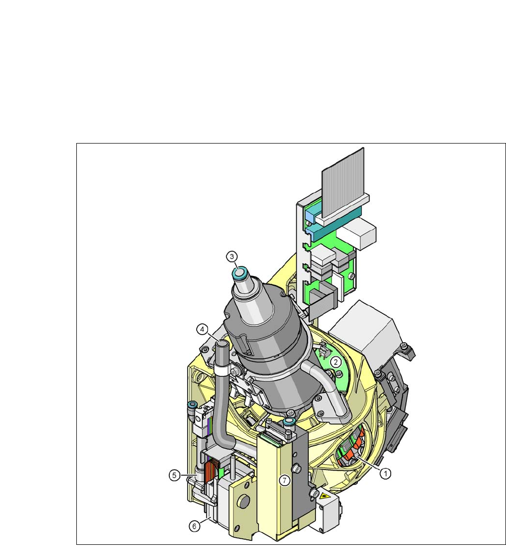
Fig. 3.7 - 1 SIPLACE SpeedStar (C&P20 M) - function groups part 1
(1) DP drive, 20 drives
(2) "Vacuum sensor hold circuit" board
(3) Compressed air connection for 20 Venturi nozzles in the pickup/placement and holding circuit
(4) Line for the exhaust air from the pressure control valve (7)
(5) Return cylinder
(6) Z motor (linear motor)
(7) Pressure control valve
3 Technical Data User Manual SIPLACE CA-Series
3.7 Placement Heads From software version SC.708.0 Edition 12/2014 EN -DRAFT
144
3
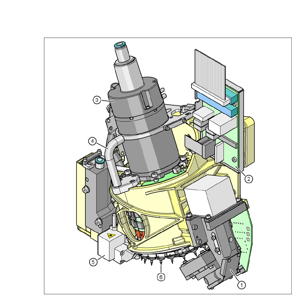
Fig. 3.7 - 2 SIPLACE SpeedStar (C&P20 M) - function groups part 2
(1) C&P component camera, type 23, 6 x 6, digital
(2) Intermediate distributor board
(3) Star motor
(4) Handle
(5) Component sensor
(6) Star with 20 nozzles

User Manual SIPLACE CA-Series 3 Technical Data
From software version SC.708.0 Edition 12/2014 EN -DRAFT 3.7 Placement Heads
145
3.7.1.1 Description
The SIPLACE SpeedStar (C&P20 M) functions according to the Collect&Place principle i.e.
twenty components are picked up by the placement head during one cycle. At the pick-up and
placement position the component sensor checks that the component is present at the nozzle. On
their way to the placement position the components are optically centered and rotated into the re-
quired placement angle. Finally forced air sets down the component gently and accurately on the
board.
The C&P20 M head makes a significant increase in the placement head performance possible
and therefore in the performance of the placement machine. The compact design of the C&P20
M head also facilitates very short cycle times. In this case, the star axis is at an angle to the PCB
level. This geometry allows the segments to be arranged in a very small space.
The component camera is still integrated into the C&P20 M head. This saves additional traveling
distances to external centering cameras. Each segment also has its own DP drive for rotating the
nozzle. The nozzles are therefore no longer rotated into the correct position at a single head sta-
tion. They can be rotated into their placement position at any time and independently of one an-
other.
Each segment has a separate vacuum generator. This greatly reduces the time taken to switch
between vacuum and air kiss. It also allows a vacuum check to be carried out in the holding circuit
for each individual nozzle.
The Z drive for the segments is implemented with a linear motor with linear path measuring sys-
tem, and is thus extremely precise. In the pick-up/placement position, the Z drive moves the seg-
ments up or down in the vertical direction.