00197498-03_UM_SiplaceCA-Serie_EN.pdf - 第318页
5 Setting up and Commissioning User Manual SIPLACE CA-Series 5.5 Setting Up the Placement Machine From software version SC.708.0 Edition 12/2014 EN -DR AFT 318 5.5.12.5 Fitting the Side Plates Fasten the grou nd cable …

User Manual SIPLACE CA-Series 5 Setting up and Commissioning
From software version SC.708.0 Edition 12/2014 EN -DRAFT 5.5 Setting Up the Placement Machine
317
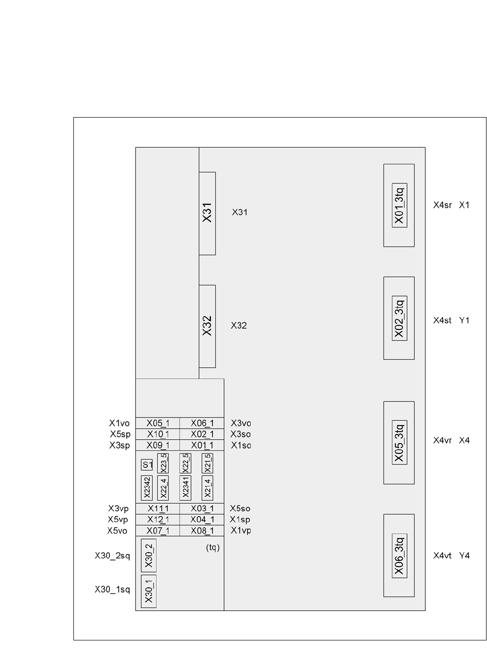
5.5.12.3 Computer Unit for CA4 - Press-Fit Connections on the Back
5
5
5.5.12.4 Fitting the Computer Unit
Establish the press-fit connections on the back of the computer unit (see section 5.5.12.3).
Carefully lift the computer unit onto the rail in the extension kit.
Make sure that you do not squash any cables.
Check that the cables to the front are run in the cable guide plate at the side
(item 1 in fig. 5.5 - 20
, page 314).
Push the computer unit into the extension kit as far as the stop.
Connect the fan cable to the computer unit cable.
Establish the press-fit connections on the front of the computer unit (see section 5.5.12.2).
Fix the cables to the front panel with cable ties.
Secure the computer unit with the fillister head screw.
Fasten the ground cable to the door (item 2 in fig. 5.5 - 14, page 303), as shown in fig. 5.5 -
16 on page 307.
Lock the doors.
5
Computer unit, rear
(fig. 5.5 - 21
)
Plug
Connection cable Please note
Plug Cable
PE1 Cable ring Grounding cable
Fasten as in fig. 5.5 - 16
,
page 307
.
X27pz X27pz 03003437 W1-W2 Insert as far as the stop
X2pz X2pz 03002966 W1-W5 Fix with screws
X1pz X1pz 03002969 W1-W5 Fix with screws
X62pz X62pz 03002488 Snap into place
PE2 Cable lug Grounding cable Insert as far as the stop
P24 / GND X1 Fan in extension kit Insert as far as the stop
PLEASE NOTE
For CA4 machines, continue with section 5.5.13 "Installing the Axis Unit on the CA4"
on page 319
.

5 Setting up and Commissioning User Manual SIPLACE CA-Series
5.5 Setting Up the Placement Machine From software version SC.708.0 Edition 12/2014 EN -DRAFT
318
5.5.12.5 Fitting the Side Plates
Fasten the ground cable to each side plate (item 6 in fig. 5.5 - 14, page 303), as shown in fig.
5.5 - 16
page 307.
Fix the side plate to the machine frame with 6 fillister head screws.
Continue with section 5.5.14 " Fitting the Main Fault Indicators", page 321.
User Manual SIPLACE CA-Series 5 Setting up and Commissioning
From software version SC.708.0 Edition 12/2014 EN -DRAFT 5.5 Setting Up the Placement Machine
319
5.5.13 Installing the Axis Unit on the CA4
5.5.13.1 Axis Unit for CA4 (Gantry 1 a 4) - Electrical Connection Points
5
Fig. 5.5 - 22 Axis unit for CA4 (gantry 1 and 4), back - connecting plug
PlugPlug
Plug