00197498-03_UM_SiplaceCA-Serie_EN.pdf - 第469页
User manual SIPLACE CA-Series 8 Station Extensions From software version SC.708.0 Edition 12/20 14 EN -DRAFT 8.1 Nozzle Changers 469 8.1.4.1 T echnical Dat a 8 Nozzle Changer for the SIPLACE T winHead Dimensions (length …
8 Station Extensions User manual SIPLACE CA-Series
8.1 Nozzle Changers From software version SC.708.0 Edition 12/2014 EN -DRAFT
468
8.1.4 Nozzle Changer for the SIPLACE TwinHead
[03005191-xx] Magazine for 2 nozzles
[03001807-xx] Magazine for 1 nozzle
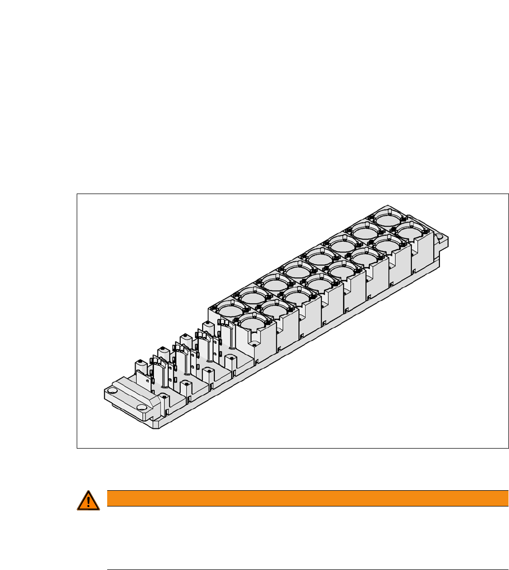
This nozzle changer can accommodate up to 12 nozzle magazines. There are two different mag-
azine types available: standard magazines and magazines for special nozzles or grippers. The
magazines are seated on a common support. They are centered with two parallel pins and fixed
in place with two countersunk screws.
8
Fig. 8.1 - 18 Nozzle Changer for the SIPLACE TwinHead
8
WARNING
Risk of head crashes with mixed configurations!
There is a risk of head crashes with mixed configurations.
Only install the corresponding nozzle changer for each placement head, with the noz-
zle magazines for the respective placement head.

User manual SIPLACE CA-Series 8 Station Extensions
From software version SC.708.0 Edition 12/2014 EN -DRAFT 8.1 Nozzle Changers
469
8.1.4.1 Technical Data
8
Nozzle Changer for the SIPLACE TwinHead
Dimensions (length x width x height) 448 x 68 x 49 mm³
Number of magazines Max. 12
Number of nozzle holders Max. 24 standard nozzles
Max. 12 special nozzles
Nozzle types 5xx, standard
4xx with adapter
9xx with adapter
Nozzle changeover time Approx. 2s per nozzle
8 Station Extensions User manual SIPLACE CA-Series
8.1 Nozzle Changers From software version SC.708.0 Edition 12/2014 EN -DRAFT
470
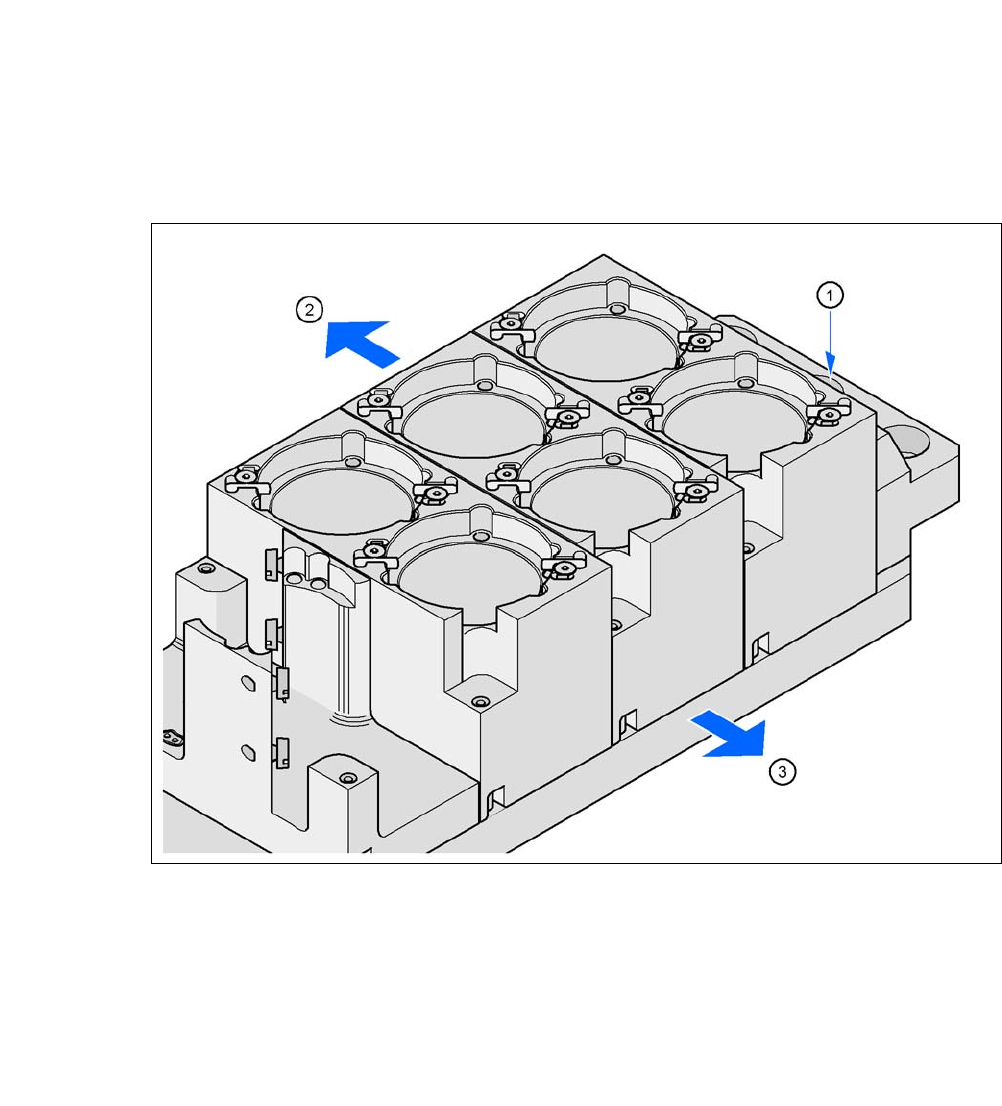
8.1.4.2 Assembly
The nozzle changer is fixed to the COT insert.
8
Fig. 8.1 - 19 Assembly position
(1) Marking hole
(2) Operator side
(3) Arrow pointing toward the PCB conveyor
8
Align the nozzle changer so that the marking hole (item 1) is on the left, as viewed by the op-
erator.