00197498-03_UM_SiplaceCA-Serie_EN.pdf - 第337页
User Manual SIPLACE CA-Series 5 Setting up and Commissioning From software version SC.708.0 Editi on 12/2014 EN -DRAFT 5.6 Fitting the SWS 337 5.6.4 Removing the T ransport Locks – Remove all transport locks: – Flip rota…
5 Setting up and Commissioning User Manual SIPLACE CA-Series
5.6 Fitting the SWS From software version SC.708.0 Edition 12/2014 EN -DRAFT
336
5
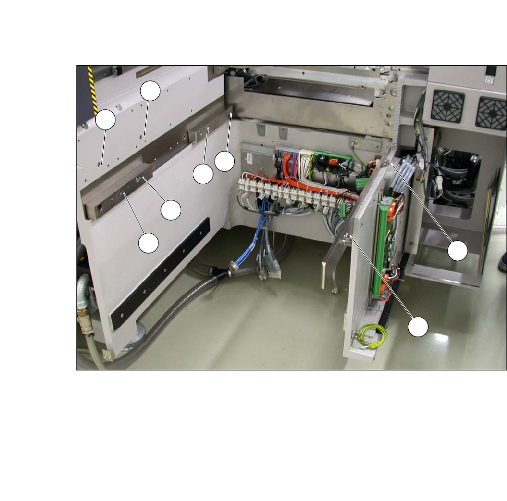
Fig. 5.6 - 4 Diagram with positions of screws for the SWS at the SIPLACE location
You can now remove the fork lift/hand lift.
(1) M8 (2) M8
(3)Fitting screw (4)M6
(5) M6 (6) M8 for clamping claw
(7) M6 for angle bracket (8) M6 for angle bracket
2
3
5
4
1
7
8
6
User Manual SIPLACE CA-Series 5 Setting up and Commissioning
From software version SC.708.0 Edition 12/2014 EN -DRAFT 5.6 Fitting the SWS
337
5.6.4 Removing the Transport Locks
– Remove all transport locks:
– Flip rotary axis
– Wafer table (X/Y axis)
– Wafer changer feed axis (if present)
5.6.5 Removing the Corrosion Protection from the Guide Rails
Check whether the SWS has been treated with corrosion protection agent. This must be removed
before setting up the SWS.
5
5
5.6.6 Power supply
After performing final adjustment, connect the SWS to the power supply.
CAUTION
Reduced product life of bearings and guide rails!
If the corrosion protection agent is mixed with the bearing grease on the axes this can
greatly reduce the service life of the bearings and guide rails.
You should therefore remove the corrosion protection from all the axes and bearings
when you traverse the machine axes for the first time during commissioning.
Grease all the axes and bearings with the grease described in the maintenance in-
structions.
CAUTION
Risk of damaging bearing grease!
Alcohol will damage the bearing grease in the guide carriages.
When cleaning the guide rails and scales, make sure that alcohol does not get into
the guide trolley.
5 Setting up and Commissioning User Manual SIPLACE CA-Series
5.7 Adapting the SIPLACE X-Series Component Trolley to the PCB Conveyor Height From software version SC.708.0 Edition 12/2014
EN -DRAFT
338
5.7 Adapting the SIPLACE X-Series Component Trol-
ley to the PCB Conveyor Height
The component trolley for the X feeder modules can be set to the following PCB conveyor heights
with just a few simple actions:
900 mm ± 15 mm, 930 mm ± 15 mm (standard height), 950 mm ± 15 mm (SMEMA height) 5
5
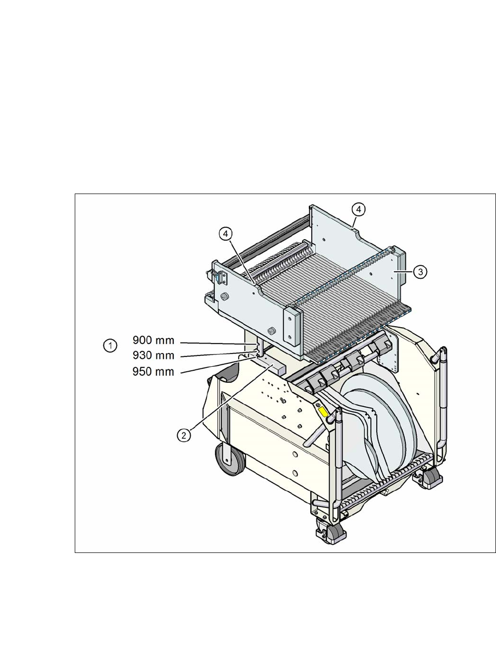
Fig. 5.7 - 1 Component trolley (SIPLACE X-Series) with a PCB conveyor height of 950 mm
(1) Holes in the guide columns for the PCB transport heights of 900, 930 and 950 mm.
(2) Support block
(3) Changeover table
(4) Contact for switching the safety switch in the COT insert