00197498-03_UM_SiplaceCA-Serie_EN.pdf - 第340页
5 Setting up and Commissioning User Manual SIPLACE CA-Series 5.7 Adapting the SIPLACE X-Series Component Trolley to the PCB Conveyor Height From software version SC.708.0 Edition 12/2014 EN -DRAFT 340 5 Fig. 5.7 - 2 Fast…
User Manual SIPLACE CA-Series 5 Setting up and Commissioning
From software version SC.708.0 Edition 12/2014 EN -DRAFT 5.7 Adapting the SIPLACE X-Series Component Trolley to the PCB Con-
veyor Height
339
5.7.1 Warning Instructions
5
5.7.2 Tools and Equipment
You will need the following tools and equipment to adjust the height of the component trolley:
– Hammer
–Punch, 8 mm
– Fit-up aid [03015976-xx]
– Lifting device for raising the component trolley table, carrying capacity at least 80 kg
5.7.3 Changing the Component Trolley Height
5
Fasten the fit-up aid (item 1 in fig. 5.7 - 2) with the two hexagon socket-head screws M8 x 50
(item 3 in fig. 5.7 - 2
) to the changeover table (item 4 in fig. 5.7 - 2).
Hook the lifting device into the eyelet (item 2 in fig. 5.7 - 2).
Lift the component trolley table slightly, until the split pins (item 6 in fig. 5.7 - 2) are accessible.
Use the punch to carefully tap out the split pins on both sides.
Insert the split pins into the holes drilled for the required PCB conveyor height (see fig. 5.7 - 1).
Slowly lower the component trolley table, until the split pins lie on the supporting blocks (item
5 in fig. 5.7 - 2
).
Dismantle the fit-up aid
WARNING
Adjustment of Component Trolley Height by Authorized Persons!
Only ASM Assembly Systems GmbH & Co.KG engineers or qualified personnel are per-
mitted to adjust the component trolley height.
Always follow the applicable accident prevention regulations.
Remove all the feeder modules from the changeover table, if you want to adjust the
height of the changeover table.
WARNING
Risk of damage!
Lifting and lowering the changeover table could lead to deformation of it.
Remove all the feeder modules from the changeover table.
Fit the fit-up aid to the changeover table in order to adjust the height.
5 Setting up and Commissioning User Manual SIPLACE CA-Series
5.7 Adapting the SIPLACE X-Series Component Trolley to the PCB Conveyor Height From software version SC.708.0 Edition 12/2014
EN -DRAFT
340
5
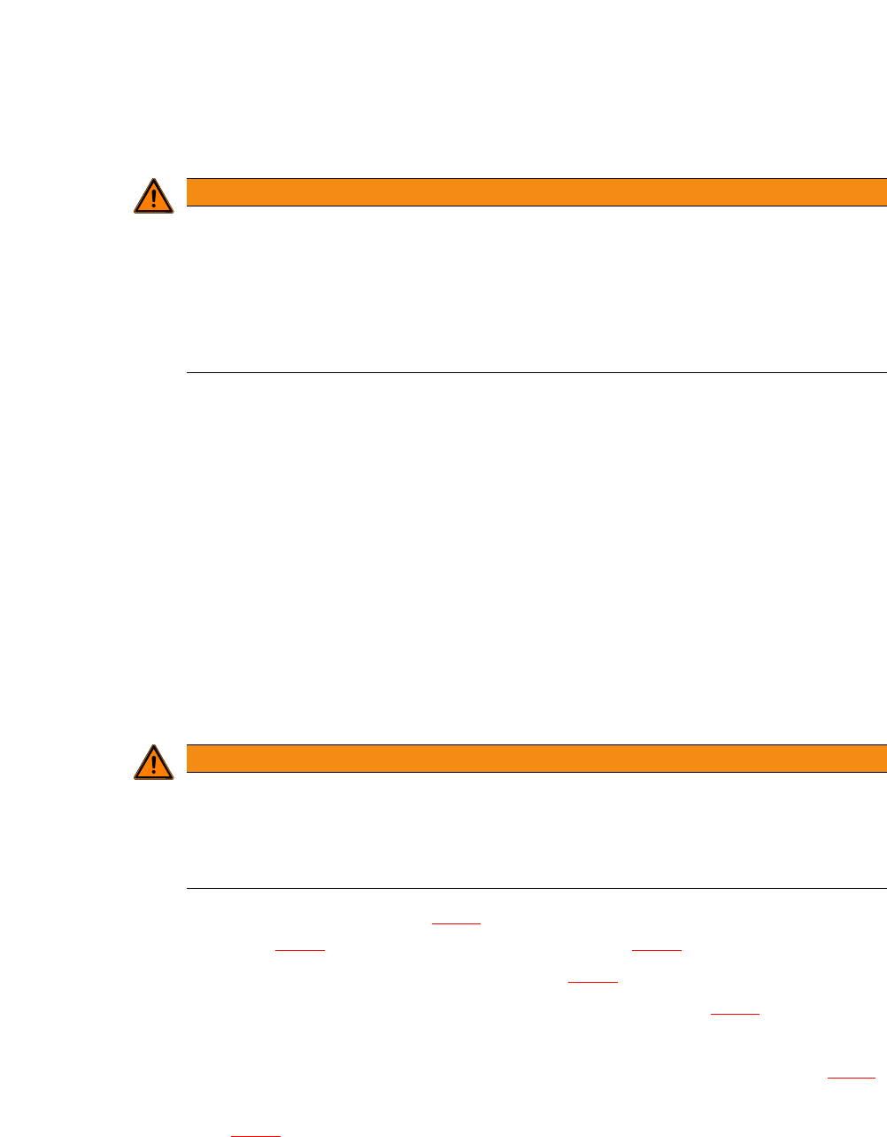
Fig. 5.7 - 2 Fastening the fit-up aid to the changeover table of the SIPLACE component trolley
(1) Fit-up aid
(2) Eyelet
(3) Hexagon socket-head screw DIN 912, M8 x 50, 2 x
(4) 2x M8 threaded hole in the component table
(5) Support block , 2x
(6) Split pin, DIN 7343, 8 x 40 - St, 2 x
User Manual SIPLACE CA-Series 5 Setting up and Commissioning
From software version SC.708.0 Edition 12/2014 EN -DRAFT 5.8 Adjusting the Length of the SIPLACE X Used Tape Chute to the PCB
Conveyor Height
341
5.8 Adjusting the Length of the SIPLACE X Used Tape
Chute to the PCB Conveyor Height
In accordance with the PCB conveyor height, the length of the used tape chute can be set so that
the tape cuttings are directly diverted into the waste tape container of the component trolley.
5
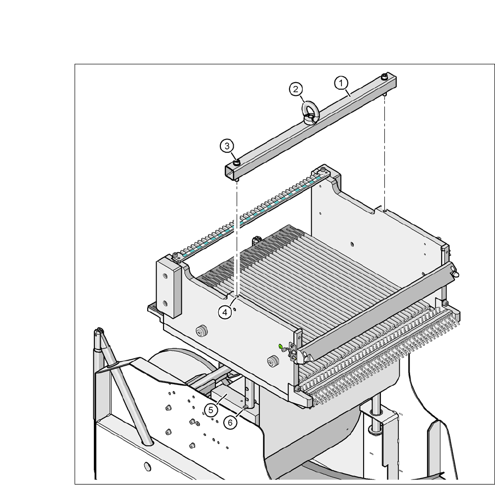
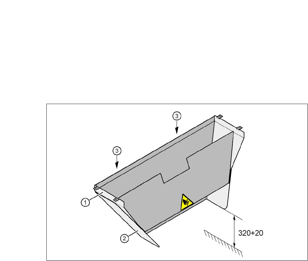
Fig. 5.8 - 1 Adapting the length of the used tape channel (X-Series) - Dimensions in millimeters
(1) Used tape chute
(2) Extension
(3) Hexagonal nut M4, DIN 985, 2 x
5.8.1 Tools
– Fork wrench, size 7