00197498-03_UM_SiplaceCA-Serie_EN.pdf - 第391页
User Manual SIPLACE CA-Series 6 Working with the Machine From software version SC.708.0 Edition 12/20 14 EN -DRAFT 6.14 Docking/Undocking the Compo nent Trolley 391 6 Fig. 6.14 - 4 X-Series component trolley - swivel han…
6 Working with the Machine User Manual SIPLACE CA-Series
6.14 Docking/Undocking the Component Trolley From software version SC.708.0 Edition 12/2014 EN -DRAFT
390
6
6
6
Carefully push the component trolley into machine as far as the stop.
6
Press the appropriate button on the input or output side of the machine (item 1, 2, 3 or 4 in
fig. 6.14 - 1
) until the component trolley has been undocked.
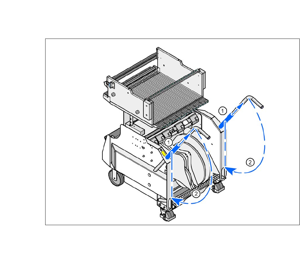
Push the sleeve (item 1 in fig. 6.14 - 4) on both handles up and swivel the handle down (item
2 in fig. 6.14 - 4
).
CAUTION
Pushing in component trolley!
Only dock the component trolley onto the COT insert designed for it.
When pushing in the component trolley for the SIPLACE X-Series into the machine,
make sure that you do not hit the locking latches (item 3 in fig. 6.14 - 3
) against any
obstacles.
PLEASE NOTE
Cut tapes flush
If you do not cut tapes off flush at the front end of the X feeder modules, the emptied tapes
will not enter the empty tape duct.
Cut the tapes off flush, before you dock the X-Series component trolley.
CAUTION
Position of placement head!
Check that the placement head is outside the range of the component trolley.
PLEASE NOTE
Docking only possible if protective cover is closed
Close the protective covers.
User Manual SIPLACE CA-Series 6 Working with the Machine
From software version SC.708.0 Edition 12/2014 EN -DRAFT 6.14 Docking/Undocking the Component Trolley
391
6
Fig. 6.14 - 4 X-Series component trolley - swivel handles down
(1) Push sleeve up
(2) Fold handle down
6 Working with the Machine User Manual SIPLACE CA-Series
6.15 Observing the Indicator Lamps for Operating States From software version SC.708.0 Edition 12/2014 EN -DRAFT
392
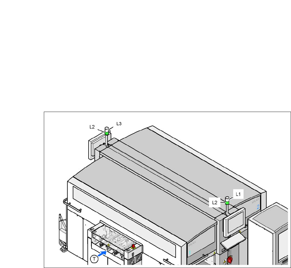
6.15 Observing the Indicator Lamps for Operating
States
The indicator lamp signals operating machine operating states and malfunctions.
6.15.1 Functions
Fig. 6.15 - 1 Operating status indicator lamp
L1 Indicator lamp (white, right)
L2 Operating status indicator lamp (green, both lamps switched parallel)
L3 Fault indicator lamp (white, left)
T Direction of PCB transport