00197498-03_UM_SiplaceCA-Serie_EN.pdf - 第145页
User Manual SIPLACE CA-Series 3 Technical Data From software version SC.708.0 Edition 12/20 14 EN -DRAFT 3.7 Placement Heads 145 3.7.1.1 Description The SIPLACE SpeedS tar (C&P20 M) functio n s according to the Colle…
3 Technical Data User Manual SIPLACE CA-Series
3.7 Placement Heads From software version SC.708.0 Edition 12/2014 EN -DRAFT
144
3
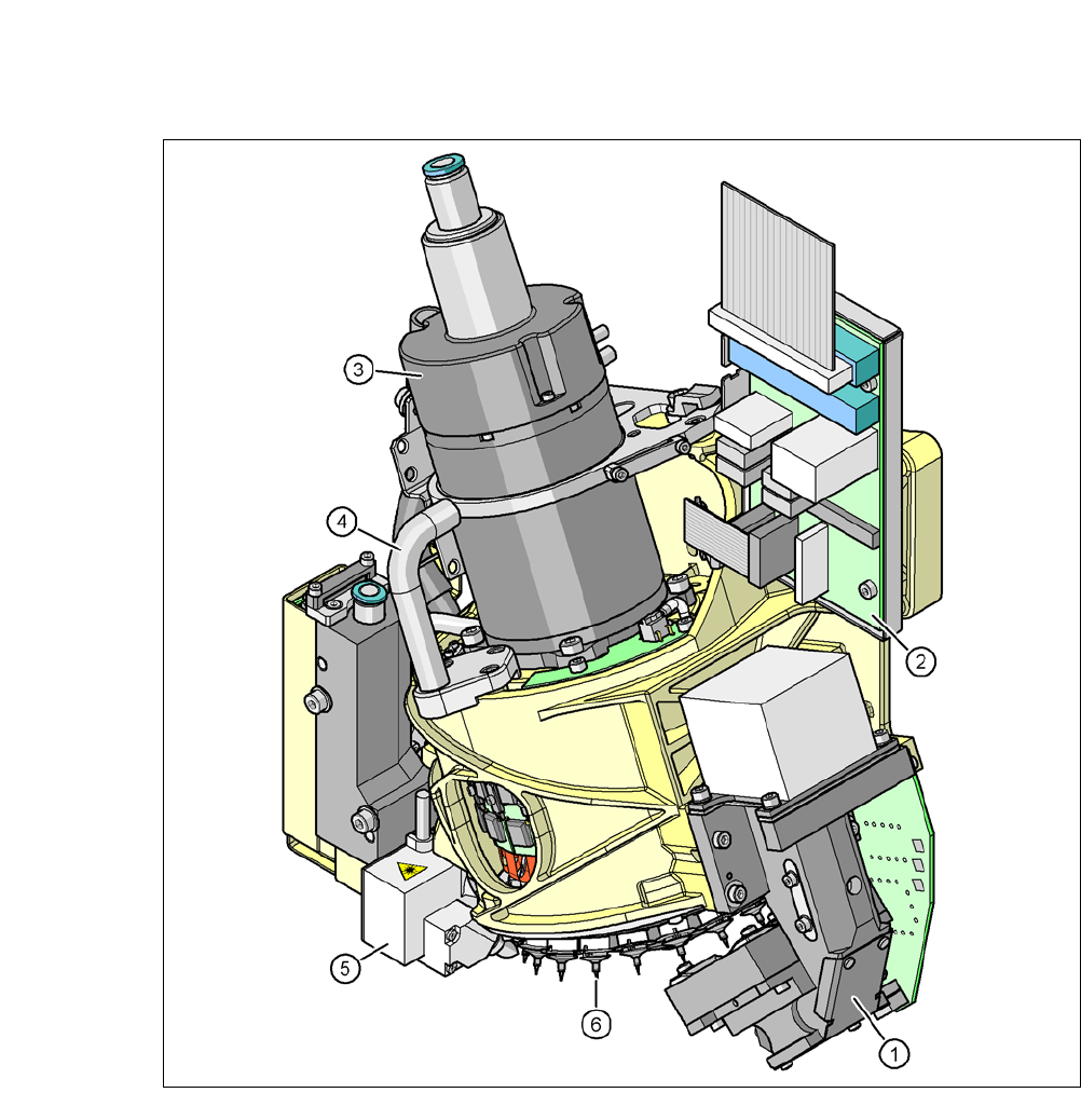
Fig. 3.7 - 2 SIPLACE SpeedStar (C&P20 M) - function groups part 2
(1) C&P component camera, type 23, 6 x 6, digital
(2) Intermediate distributor board
(3) Star motor
(4) Handle
(5) Component sensor
(6) Star with 20 nozzles

User Manual SIPLACE CA-Series 3 Technical Data
From software version SC.708.0 Edition 12/2014 EN -DRAFT 3.7 Placement Heads
145
3.7.1.1 Description
The SIPLACE SpeedStar (C&P20 M) functions according to the Collect&Place principle i.e.
twenty components are picked up by the placement head during one cycle. At the pick-up and
placement position the component sensor checks that the component is present at the nozzle. On
their way to the placement position the components are optically centered and rotated into the re-
quired placement angle. Finally forced air sets down the component gently and accurately on the
board.
The C&P20 M head makes a significant increase in the placement head performance possible
and therefore in the performance of the placement machine. The compact design of the C&P20
M head also facilitates very short cycle times. In this case, the star axis is at an angle to the PCB
level. This geometry allows the segments to be arranged in a very small space.
The component camera is still integrated into the C&P20 M head. This saves additional traveling
distances to external centering cameras. Each segment also has its own DP drive for rotating the
nozzle. The nozzles are therefore no longer rotated into the correct position at a single head sta-
tion. They can be rotated into their placement position at any time and independently of one an-
other.
Each segment has a separate vacuum generator. This greatly reduces the time taken to switch
between vacuum and air kiss. It also allows a vacuum check to be carried out in the holding circuit
for each individual nozzle.
The Z drive for the segments is implemented with a linear motor with linear path measuring sys-
tem, and is thus extremely precise. In the pick-up/placement position, the Z drive moves the seg-
ments up or down in the vertical direction.

3 Technical Data User Manual SIPLACE CA-Series
3.7 Placement Heads From software version SC.708.0 Edition 12/2014 EN -DRAFT
146
3.7.1.2 Control and Self-Learning Functions
Control and self-learning functions improve the reliability of the SIPLACE SpeedStar (C&P20 M).
– The vertical axis for picking up and placing components is driven by a linear motor. The
travel range is recorded opto-electronically by a linear path measuring system. A sensor
registers the relative movement between the nozzle and the segment when components
are placed and sends a signal to the position control axes. With this sensor stop method,
differences in height during pickup and any unevenness of the board surface are com-
pensated during placement. The average of the deviations during the last 10 placement
operations is taken into account when adapting the further stroke and placement speeds.
The programmed placement force always remains constant.
– To increase the placement reliability, a component sensor has been installed on the SI-
PLACE SpeedStar (C&P20 M). At the pickup and placement position, it checks that the
component is present at the nozzle and in addition the component edge ratio. In this way
it is possible to determine whether the component was picked up by the nozzle trans-
versely or on edge. The beam intensity is also checked regularly to avoid false measure-
ments.
– The package form is also checked and the component is not placed if the geometric data
thus determined differs from the programmed data.
– A digital component camera on the placement head determines the precise position of
each component at the nozzle. The standard camera, type 23 of the SIPLACE SpeedStar
(C&P20 M) can optically center components with the dimensions 0.2 mm x 0.2 mm up to
6 mm x 6 mm. Variations of the transfer position are corrected already before placing.
When a component is picked up, the average of the deviations for the last 10 placement
operations is taken into account, thus increasing the pickup accuracy.
3.7.1.3 Functions
The SIPLACE SpeedStar (C&P20 M) has three axes, the DR or star axis, the Z axis and the DP
axis.