00197498-03_UM_SiplaceCA-Serie_EN.pdf - 第490页
8 Station Extensions User manua l SIPLACE CA-Series 8.8 PCB alignment From software version SC.708.0 Edition 12/2014 EN -DR AFT 490 8.8 PCB alignment [001 19677-xx] PCB alignment single conveyor , SIPLACE HF/X/CA/D3 [001…

User manual SIPLACE CA-Series 8 Station Extensions
From software version SC.708.0 Edition 12/2014 EN -DRAFT 8.7 PCB Barcode Scanner
489
8
8
8
8
8
8
8
Dimensions 55 mm x 42 mm x 22 mm
(2.17 inch x 1.65 inch x 0.87 inch)
Weight 125 g ( 0.28 lb)
Ambient conditions
Operating temperature 0 ºC to 40 ºC (32 ºF to 104 ºF)
Humidity (operation) 95 % (not condensing)
Storage temperature -10 ºC to 60 ºC (-14 ºF to 140 ºF)
Humidity (storage) 95 % (not condensing)
Protection class IP-65
Vibration EN61373, inc. IEC 60068-2-6,60068-2-64 6.4 and
60068-2-27
Certificates
Approvals CE, UL, FCC, CTICK, VCCI, IC
8 Station Extensions User manual SIPLACE CA-Series
8.8 PCB alignment From software version SC.708.0 Edition 12/2014 EN -DRAFT
490
8.8 PCB alignment
[00119677-xx] PCB alignment single conveyor, SIPLACE HF/X/CA/D3
[00119678-xx] PCB conveyor dual conveyor, SIPLACE HF/X/CA/D3
8.8.1 General
PCBs to be processed sometimes have a length to width ratio of 1:2 or worse. This means that
the shorter side of the PCB points in the direction of travel. During travel, such PCBs may twist
slightly and, as a result, the fiducials no longer lie within the PCB vision camera's search window.
In this case, the "PCB alignment" option ensures that these PCBs are realigned precisely at the
stopping position.
If boards with recesses are processed in the direction of transport, this could lead to different pro-
cessing positions in machines with mechanical stoppers (HS-50, S-25 HM, F5 HM) and in ma-
chines which monitor this position with the laser light barrier (X-, CA-, HF-Series, HS-60, S-27
HM). The "PCB alignment" option ensures that the PCBs are stopped at the same position on all
PCB conveyors. The "PCB alignment" option is available for both single and dual conveyors.
8
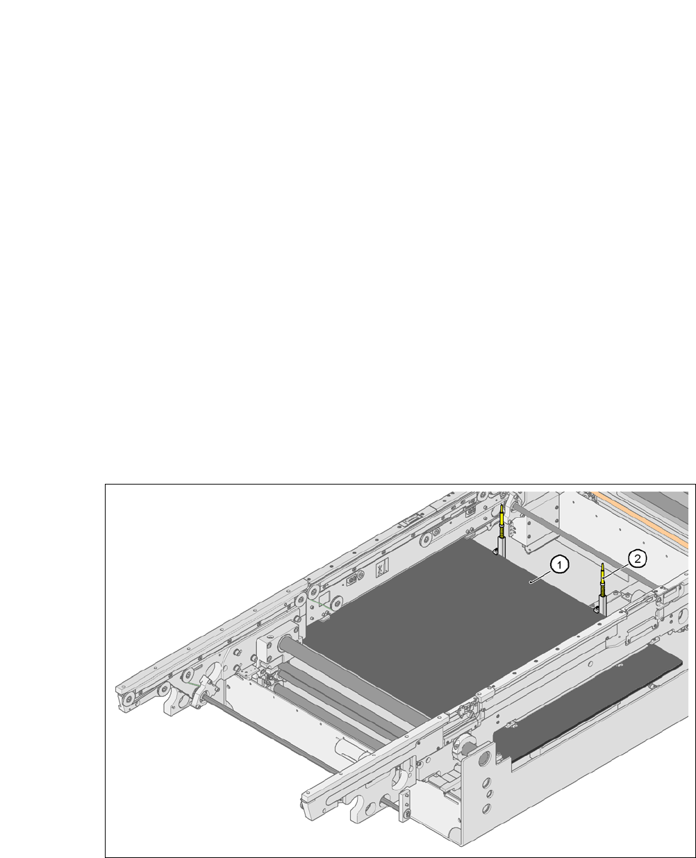
Fig. 8.8 - 1 PCB alignment
(1) Lifting table
(2) PCB stop

User manual SIPLACE CA-Series 8 Station Extensions
From software version SC.708.0 Edition 12/2014 EN -DRAFT 8.9 Siemens Interface
491
8.8.2 Functions
The PCB is transported into the placement area until the laser light barrier triggers the stop signal
for the PCB conveyor. The lifting table with the PCB stops then moves up into a position in which
the PCB is not yet clamped and can still be moved by the conveyor belts. The two PCB stops are
level with the PCB, and the PCB supports (magnetic pins) are already in contact with the PCB.
The two conveyor belts move the PCB against the PCB stops and align them at the same time.
The lifting table then moves into its top end position, clamps the PCB and releases it from the PCB
stops so as not to affect the placement process. After the placement process, the lifting table and
PCB alignment are lowered and the PCB is moved on.
8
8.9 Siemens Interface
[00116808-xx] SIPLACE Interface HF/X/CA/D3
The conveyor interface on the placement machines from the CA-Series is configured to the
SMEMA
standard. It is, however, still possible to use this interface in accordance with the Siemens stan-
dard. This is a significant benefit when a CA-Series machine is to be integrated into older SI-
PLACE
lines, in which case it would not be necessary to retrofit the older machines to conform to the
SMEMA standard.
Simply configure the conveyor interface of the CA-Series machines to the Siemens standard and
connect the machines using the associated interface cable.
For more information, refer to the "Retrofitting Guide for Siemens Conveyor Interfaces"
[00194343-01].