00197498-03_UM_SiplaceCA-Serie_EN.pdf - 第169页
User Manual SIPLACE CA-Series 3 Technical Data From software version SC.708.0 Edition 12/20 14 EN -DRAFT 3.9 Controls on the Placement Machine 169 3.9.2 Description All the controls can be reached by a 1.40 m t all perso…
3 Technical Data User Manual SIPLACE CA-Series
3.9 Controls on the Placement Machine From software version SC.708.0 Edition 12/2014 EN -DRAFT
168
3.9 Controls on the Placement Machine
3.9.1 Controls and Displays
3
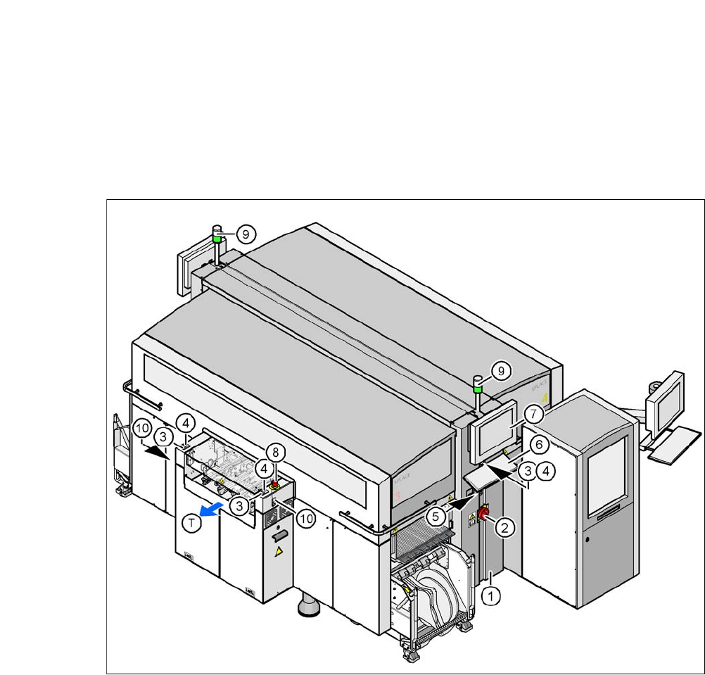
Fig. 3.9 - 1 Controls and displays
(1) Operator panel on the power supply side (7) LCD touchscreen
(2) Main switch (8) EMERGENCY STOP button
(3) Stop button (black) (9) Indicator lamps
(4) Start button (white) (10) Button for docking and undocking the
component trolley
(5) Component counter
(6) Keyboard (T) Direction of PCB transport

User Manual SIPLACE CA-Series 3 Technical Data
From software version SC.708.0 Edition 12/2014 EN -DRAFT 3.9 Controls on the Placement Machine
169
3.9.2 Description
All the controls can be reached by a 1.40 m tall person.
Main switch 3
The main switch is used for switching the power supply to the placement machine on and off.
3
Stop button 3
This button stops placement operations at the placement machine.
Start button 3
This button starts the placement machine after it has been switched on or after malfunctions have
been fixed.
EMERGENCY STOP button 3
The EMERGENCY STOP button latches in the ON position when pressed. The power supply to
the gantry axes, the component trolleys, conveyors and used tape cutters is interrupted and the
voltage supplied to the star axes of the placement heads is reduced. Turn the button to release it.
Component counter 3
The component counter displays the number of components processed in increments of ten.
LCD monitor 3
Each side of the placement machine features a flat screen monitor with LCD technology and
touchscreen function.
Keyboard 3
The keyboard is located beneath the monitor.
DANGER
Lethal voltages!
Some parts inside the machine carry potentially lethal voltages - even when switched off
at the main power switch.
Always follow the applicable accident prevention and DIN regulations (particularly EN
60204, part 1 or IEC 60204, part 1) and the applicable regulations in your own coun-
try.
Only qualified or appropriately trained personnel may switch the power supply to the
placement machine on and off.

3 Technical Data User Manual SIPLACE CA-Series
3.9 Controls on the Placement Machine From software version SC.708.0 Edition 12/2014 EN -DRAFT
170
Indicator lamps 3
The sequence of colors of the indicator lamps is white - green. These lamps are used to signal
operating statuses and malfunctions of the machine.
3.9.3 Ergonomic Arrangement of Controls
Fig. 3.9 - 1, page 168 gives an overview of where the controls are located. They are subdivided
into the following groups:
Operator panel on right side (pneumatic unit) of the central compartment with 3
– LCD touchscreen
– Keyboard with trackball
– Start button, Stop button
Operator panel on left side (power supply unit) of the central compartment with 3
– LCD touchscreen
– Keyboard with trackball
– Component counter
– Start button
– Stop button
– Main switch
PCB conveyor input and output sides with 3
– EMERGENCY STOP button
– Start button, Stop button
– Button for docking and undocking the component trolley