00197498-03_UM_SiplaceCA-Serie_EN.pdf - 第335页
User Manual SIPLACE CA-Series 5 Setting up and Commissioning From software version SC.708.0 Editi on 12/2014 EN -DRAFT 5.6 Fitting the SWS 335 5.6.3.4 Final Adjustment of SWS Use the fork-lif t truck or hand lift to pu…
5 Setting up and Commissioning User Manual SIPLACE CA-Series
5.6 Fitting the SWS From software version SC.708.0 Edition 12/2014 EN -DRAFT
334
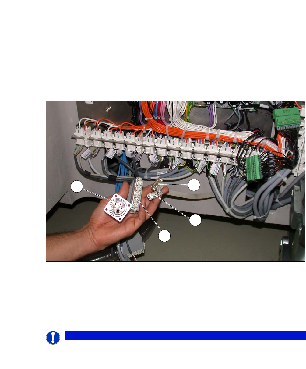
5.6.3.3 Connecting the SWS to the Placement Machine
The SWS connections need to be connected as follows to the placement machine:
– CAN Bus connections X1x6 and X1x5
– Compressed air connection to compressed air connection
– FFI communication interface W11 to FFI communication interface X1x3
5
Fig. 5.6 - 3 Position of the connections on the placement machine
(1) CAN Bus connection X1x5
(2) CAN Bus connection X1x6
(3) Compressed air connection (modified dummy connector [03011592-01])
(4) FFI communication connection X1x3
5
PLEASE NOTE
Connection points no longer accessible after installation
Connect the SWS to the placement machine before performing alignment and final
adjustments.
1
2
3
4
User Manual SIPLACE CA-Series 5 Setting up and Commissioning
From software version SC.708.0 Edition 12/2014 EN -DRAFT 5.6 Fitting the SWS
335
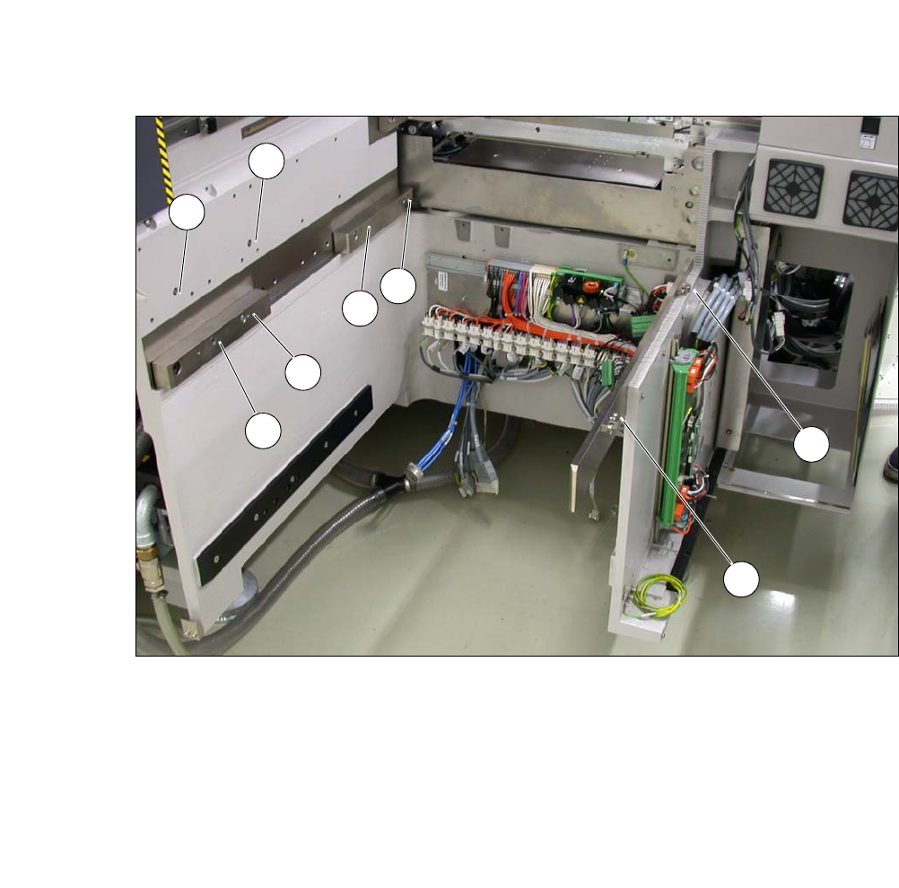
5.6.3.4 Final Adjustment of SWS
Use the fork-lift truck or hand lift to push the SWS carefully into the placement machine, as
far as the stop on the bumper.
Carefully lower the SWS with the fork-lift truck or hand lift, until it lies evenly on the contact
bars of the placement machine.
5
The following screws are needed to install the SWS :
–3x M8
–2x M6
– 4 M6 for the angle bracket (2 at the location, 2 at the wafer table)
– 1x fitting screw
5
Fasten the back clamping claw (6) loosely with an M8 screw.
Insert the remaining screws and tighten loosely.
5
Fasten the M6 screws (item 4 and 5) in succession, with a torque of 10 Nm.
Fasten the M8 screws (item 1, 2 and 6) in succession, with a torque of 18 Nm.
Tighten the fitting screw in item 3 with a torque of 13-14 Nm.
Tighten the angle bracket for fixing the wafer table with the M6 screws (items 7 and 8).
Fix the angle bracket with the 2 M6 screws to the wafer table.
CAUTION
Risk of tilting!
When lowering the hand lift before the screws of the SWS have been tightened, there is
a risk that the SWS could tilt.
Do not lower the hand lift too far before the SWS screws have been tightened.
Enlist the help of a second person to check the stability of the SWS during lowering.
PLEASE NOTE
Order of screws
During final installation, observe the following order of screws.
PLEASE NOTE
The correct position of the SWS is ensured with the help of the fitting screw and the con-
tact rods in the placement machine.
5 Setting up and Commissioning User Manual SIPLACE CA-Series
5.6 Fitting the SWS From software version SC.708.0 Edition 12/2014 EN -DRAFT
336
5
Fig. 5.6 - 4 Diagram with positions of screws for the SWS at the SIPLACE location
You can now remove the fork lift/hand lift.
(1) M8 (2) M8
(3)Fitting screw (4)M6
(5) M6 (6) M8 for clamping claw
(7) M6 for angle bracket (8) M6 for angle bracket
2
3
5
4
1
7
8
6