00197498-03_UM_SiplaceCA-Serie_EN.pdf - 第438页
7 Component and Die Handling User Manual SIPLACE CA-Series 7.5 Docking Station for the SIPLACE X-Series Component Tr olley From software version SC.708.0 Edition 12/2014 EN -DRAFT 438 7.5 Docking S t ation for the SIPLAC…
User Manual SIPLACE CA-Series 7 Component and Die Handling
From software version SC.708.0 Edition 12/2014 EN -DRAFT 7.4 Used Tape Chute - Component Trolley Docking Unit for SIPLACE X-
Series
437
7.4.2 Dismantling the Partition Plate for Tape Pocket Heights > 12 mm
If you use X feeder modules which process tape with a pocket height of > 12 mm, you will need
to remove the partition plate (item 3 in fig. 7.4 - 1
).
7
Loosen the two hexagon screws (item 4 in fig. 7.4 - 1)
Pull out the separating plate.
7
7
WARNING
Removing the separating plate!
Switch the machine off at the main switch to remove the dividing plate.
Disconnect the machine from the power and compressed air supply.
Lock the machine to prevent unauthorized reactivation, as described in section 2.12,
page 114
.
Wait until the operating pressure for the tape cutter has dropped to 0 MPa.
Do not reach inside the empty tape duct.
PLEASE NOTE
Risk of blockages!
When using feeder modules with low pockets next to feeder modules with high pockets,
there is a risk of blockages in the empty tapes.
Do not position feeder modules with shallow pockets immediately beside feeder mod-
ules with deep pockets.
7 Component and Die Handling User Manual SIPLACE CA-Series
7.5 Docking Station for the SIPLACE X-Series Component Trolley From software version SC.708.0 Edition 12/2014 EN -DRAFT
438
7.5 Docking Station for the SIPLACE X-Series Compo-
nent Trolley
[00116933-xx] Docking station for SIPLACE X component trolley
7.5.1 Overview
The docking station is an additional component for the setup area. It forms the link between the
setup area and the component trolley for the SIPLACE X-Series. The docking station allows the
component trolleys to be set up with feeder modules and function tests and setup checks to be
carried out externally.
7
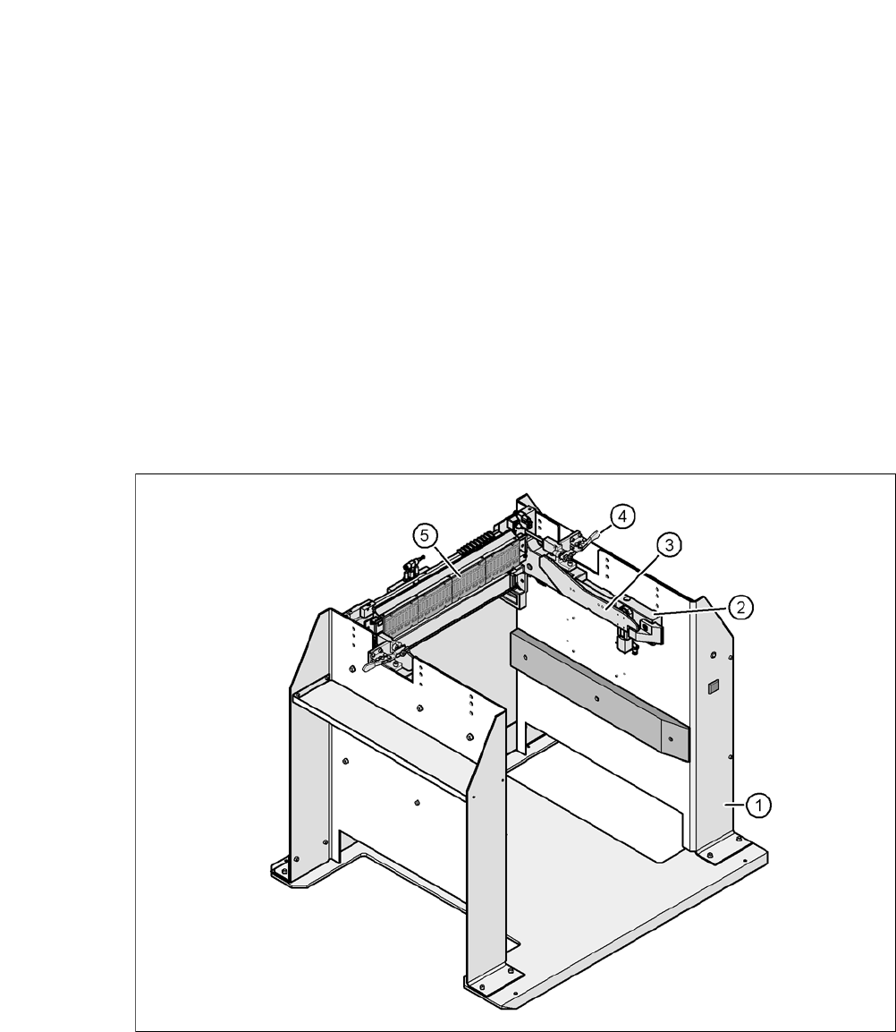
Fig. 7.5 - 1 Docking station, SIPLACE X-Series
(1) Docking station
(2) X-Series COT insert
(3) Rails for guiding and docking the changeover table
(4) Clamping lever for locking the component trolley
(5) EDIF (energy and data interface)

User Manual SIPLACE CA-Series 7 Component and Die Handling
From software version SC.708.0 Edition 12/2014 EN -DRAFT 7.5 Docking Station for the SIPLACE X-Series Component Trolley
439
The main tasks performed by the docking station are as follows:
– Supply of energy to the component trolley and X feeder modules
– Supply of compressed air to the component trolley and X feeder modules
– Provision of an infrastructure for communication between the pre-setup location PC and
the feeder modules
7.5.2 Functions
With the help of the docking station, the operator can perform function tests to the X feeder mod-
ules outside the production environment and can check the setup. There are two rows, each with
four docking stations, connected via the CAN bus of the pre-setup PC. Each docking station has
its own power and compressed air connection.
The component trolley COT insert (item 2 in fig. 7.5 - 1
) for the docking station can be adjusted to
the required PCB conveyor height. To perform the pre-setup tasks, the component trolley is
pushed into the docking station (item 1 in fig. 7.5 - 1
). The component trolley slides along the COT
insert rails, with the roller bearings on the side of the component trolley, up to the energy and data
interface connection. The changeover table and feeder EDIF are aligned in the optimum position
to the EDIF (item 4 in fig. 7.5 - 1
, page ) of the COT insert and fixed in this position with the two
clamping levers.
7.5.3 Technical Data
7
Dimensions
Length x width 950 mm x 930 mm
Height 864 mm for 900 mm PCB conveyor height
894 mm for 930 mm PCB conveyor height
914 mm for 950 mm PCB conveyor height
Weight 120 kg
Compressed air pressure val-
ues
p
min
p
max
0.5 MPa (5.0 bar)
1.0 MPa (10.0 bar)
Compressed air connection Connection plug KS 2-M5-A
Compressed air consumption 50 Nl/min
*a
*)a Under normal atmospheric conditions at 20°C and 1013 hPa
Supply voltage 88 - 264 V~
Rated current 3.5 A (230 V~)
7 A (115 V~)
Nominal apparent power 0.8 kW
Fuse 2 x 8 A