00197498-03_UM_SiplaceCA-Serie_EN.pdf - 第224页
4 SIPLACE Wafer System (SWS) User Manual SIPLACE CA- Series 4.3 Description of the SWS Modules From software version SC.708.0 Edition 12/2014 224 4 Fig. 4.3 - 8 Die ejector base unit (1) Z axis (2) Z axis movement (pneum…
User Manual SIPLACE CA-Series 4 SIPLACE Wafer System (SWS)
From software version SC.708.0 Edition 12/2014 4.3 Description of the SWS Modules
223
4.3.5 Die Ejector
According to the location (2 and 4 or 1 and 3) there are two different variants that only differ in their
mirror-inverted arrangement of the modules.
4
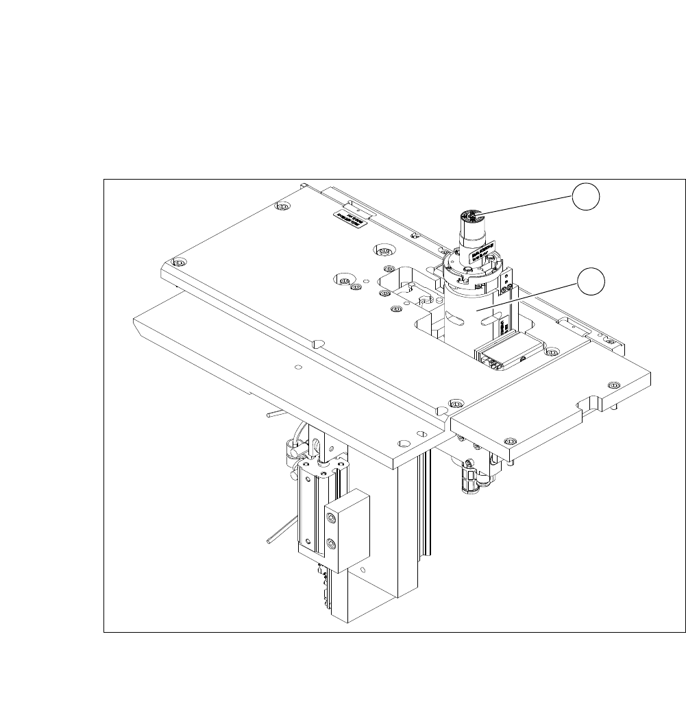
Fig. 4.3 - 7 Main die ejector modules
(1) Ejector tool
(2) Z axis
1
2
4 SIPLACE Wafer System (SWS) User Manual SIPLACE CA-Series
4.3 Description of the SWS Modules From software version SC.708.0 Edition 12/2014
224
4
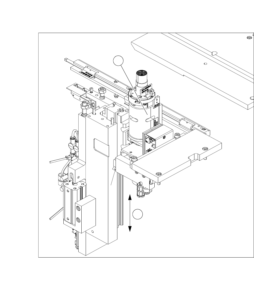
Fig. 4.3 - 8 Die ejector base unit
(1) Z axis
(2) Z axis movement (pneumatic)
1
2
User Manual SIPLACE CA-Series 4 SIPLACE Wafer System (SWS)
From software version SC.708.0 Edition 12/2014 4.3 Description of the SWS Modules
225
4.3.6 Ejector Tool
4
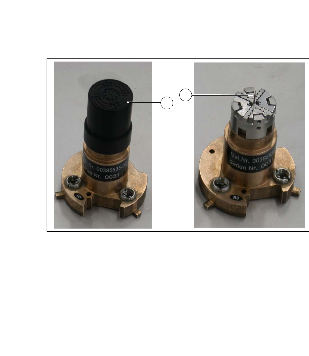
Fig. 4.3 - 9 Ejector tool
(1) Vacuum cap
(2) Ejection needle
The die ejector is used to release the die from the wafer foil. It consists of a base unit and the ejec-
tor tool.
The ejector tool is fitted to the base unit and consists of the interface, the needle system and a
vacuum cap.
The wafer foil is picked up by vacuum suction at the vacuum cap, the needle system moves up
and releases the die from the wafer foil. The die can now be taken up by the nozzle of the flip unit.
The ejector tool needs to be adjusted to the size of the die and can therefore be exchanged to suit
requirements. It is fixed to the base unit by a bayonet connection..
The ejector tool can be equipped with 2 different needle types:
– Non-piercing needles
These cause the wafer foil to curve upwards and so release the die. The wafer foil is not
pierced in this case, so that the components are not touched by the needles.
– Piercing needles
These pierce the foil and lift the die directly off the foil.
1
2