00197498-03_UM_SiplaceCA-Serie_EN.pdf - 第217页
User Manual SIPLACE CA-Series 4 SIPLACE Wafer System (SWS) From software version SC.708.0 Edition 12/2014 4.3 Description of the SWS Modules 217 4.3.2 Flip Unit 4 Fig. 4.3 - 2 Flip Unit 4 4 (1) Flip head (2) Nozzle or to…
4 SIPLACE Wafer System (SWS) User Manual SIPLACE CA-Series
4.3 Description of the SWS Modules From software version SC.708.0 Edition 12/2014
216
4.3 Description of the SWS Modules
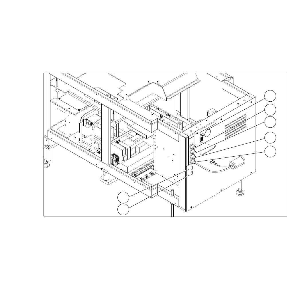
4.3.1 Supply Unit
4
Fig. 4.3 - 1 Supply unit
4
(1) Manometer for compressed air supply (2) Voltage supply
(3) Communication with SIPLACE machine (4) CAN bus
(5) Compressed air connection (modified
adapter dummy connector [03011592-01])
(6) LAN1
(7) LAN2
2
1
3
4
5
6
7
User Manual SIPLACE CA-Series 4 SIPLACE Wafer System (SWS)
From software version SC.708.0 Edition 12/2014 4.3 Description of the SWS Modules
217
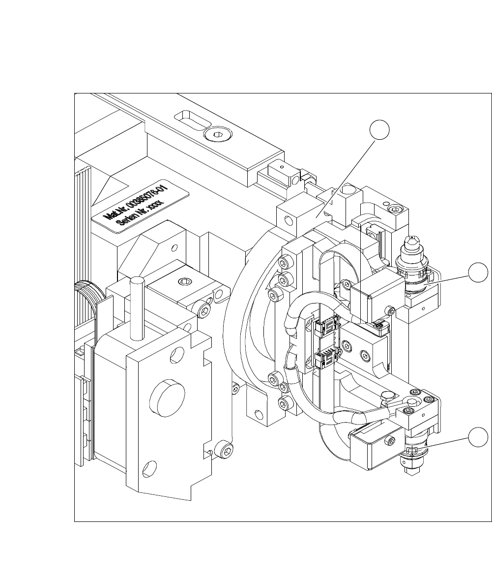
4.3.2 Flip Unit
4
Fig. 4.3 - 2 Flip Unit
4
4
(1) Flip head (2) Nozzle or tool take-up
1
2
2
4 SIPLACE Wafer System (SWS) User Manual SIPLACE CA-Series
4.3 Description of the SWS Modules From software version SC.708.0 Edition 12/2014
218
4
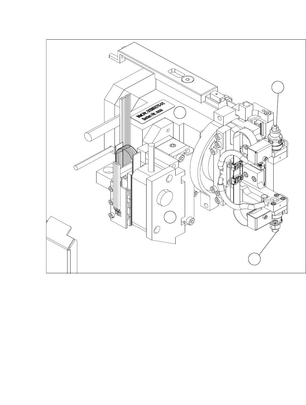
Fig. 4.3 - 3 Flip head - view from front
(1) Nozzle take-up, segment 1
(2) Nozzle take-up, segment 2
(3) Motor for linear movement
(4) Motor for 180° rotation
The flip unit takes the ejected die from the wafer foil. In flip chip mode, it rotates the die by 180°
into the pickup position for the placement head. In die attach mode, the flip unit rotates the die by
approx. 130° into the transfer position for the die attach unit.
The flip unit has two nozzles arranged at 180° to one another. This enables the system in flip chip
mode to pick up a new die from the wafer at the same time as the placement head performs
pickup.
The flip unit can use both the standard SIPLACE nozzles (9xx) and the special adapters for the
die bonding tool. As in the case of other SIPLACE placement machines, the dies are attached to
the nozzles by a vacuum.
1
3
4
2