00197498-03_UM_SiplaceCA-Serie_EN.pdf - 第347页
User Manual SIPLACE CA-Series 6 Working with the Machine From software version SC.708.0 Edition 12/2014 EN -DRAFT 6.2 The User Interface 347 6.2 The User Interface The user interface is divided into the following areas. …

6 Working with the Machine User Manual SIPLACE CA-Series
6.1 Staff Profiles From software version SC.708.0 Edition 12/2014 EN -DRAFT
346
6.1.3 Operator Level "Service (Customer)"
6.1.3.1 Tasks
The service personnel's duties include:
– Major preventive maintenance jobs
– Mounting replacement parts
– Editing machine data
– Calibrating the machine
6.1.4 Operator Level "Service (SIPLACE)"
6.1.4.1 Tasks
The programmer's jobs are as follows:
– Preparing CAD files
– Creating and calibrating vision data (teaching)
– Writing placement programs
– Implementing a new job
– Data maintenance
– Data backup
User Manual SIPLACE CA-Series 6 Working with the Machine
From software version SC.708.0 Edition 12/2014 EN -DRAFT 6.2 The User Interface
347
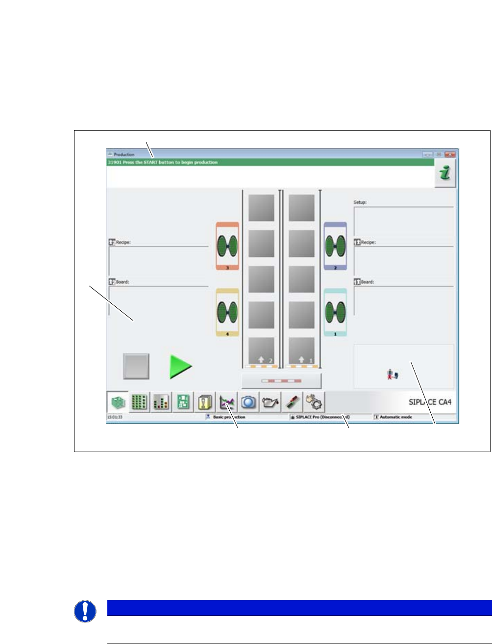
6.2 The User Interface
The user interface is divided into the following areas.
6
Fig. 6.2 - 1 User interface components in the "Production" (example of SIPLACE CA4 shown) view
Legend
(1) Status field (status and error display)
(2) Processing area / display area
(3) Toolbar
(4) Information line
(5) View of changed configurations and additional options e.g. barcode mode
6
PLEASE NOTE
For a detailed description of the user interface and of individual functions, refer to the On-
line Help for the station computer software.
(1)
(2)
(3)
(4)
(5)

6 Working with the Machine User Manual SIPLACE CA-Series
6.2 The User Interface From software version SC.708.0 Edition 12/2014 EN -DRAFT
348
6.2.1 Status Field
The status field shows the current machine status, the error which occurred most recently and the
action to be performed.
The right-hand side of the status field shows the status with the following icons:
(Green) Starts the context-sensitive Online Help function for the current view. All operating con-
trols for the current view are explained
(Red) Starts the help system, showing possible causes of the current error and measures for solv-
ing the fault.
Opens a dialog window in which the error source, the error notification text and the date and time
of error occurrence is shown. The help function for the current error can also be opened from here.
Opens a detailed view for the current error. Troubleshooting measures can be directly opened
from this view (only shown for certain error messages).
Deletes the error currently shown from the status field.
6.2.2 Display and Processing Area
This area shows the buttons for setting/deleting functions, general information about the board,
setup, recipes and other information.
Animated and color-coded items helps explain processes or states (e.g. editing, empty location
etc.).
The "Production" (basic view) view indicates certain operating states (editing, error etc.).
Stop processing. This stops the current processing run.
Continue processing. This starts or continues board placement.
Progress bar
The placement progress is shown for each board on the progress bar.
Boards being processed
The board is taken up by the system and placed. The PCB icon will be shown as a dark green
button.