00197498-03_UM_SiplaceCA-Serie_EN.pdf - 第370页
6 Working with the Machine User Manual SIPLACE CA-Series 6.7 Configuring the Feeder Modules From software version SC.708.0 Edition 12/2014 EN -DR AFT 370 6.7 Configuring the Feeder Modules 6.7.1 Notes on Handl ing Feeder…
User Manual SIPLACE CA-Series 6 Working with the Machine
From software version SC.708.0 Edition 12/2014 EN -DRAFT 6.6 Performing a Sight Check
369
6.6.6 Using Spindles for Large Tape Reels
6
6
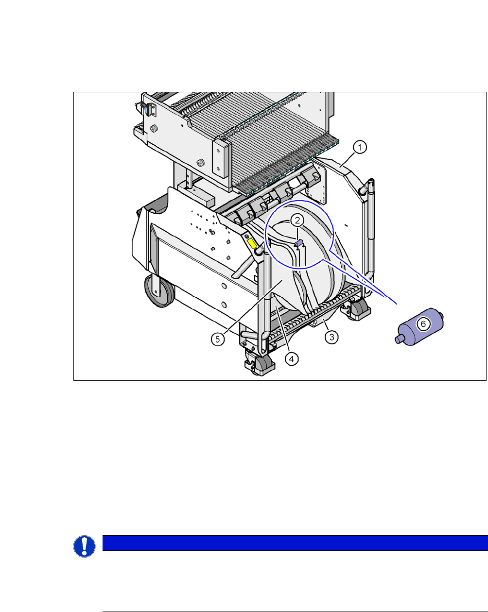
Fig. 6.6 - 4 SIPLACE X-Series component trolley, with tape container and spindle
(1) Component trolley
(2) Position of the spindle
(3) Waste tape container
(4) Tape container
(5) Separating plate
(6) Spindle (zoom)
6
PLEASE NOTE
Using spindles
SIPLACE X-Series component trolleys do not generally need spindles.
Use spindles if the error message "Timeout" appears frequently on the X feeder mod-
ule.
6 Working with the Machine User Manual SIPLACE CA-Series
6.7 Configuring the Feeder Modules From software version SC.708.0 Edition 12/2014 EN -DRAFT
370
6.7 Configuring the Feeder Modules
6.7.1 Notes on Handling Feeder Modules
Feeder modules are precision devices. You should therefore handle the feeder modules with care.
Avoid bumping feeder modules into obstacles.
Do not drop the feeder modules.
Always use suitable tools for preventive maintenance.
6.7.2 Removing X Feeder Modules from the Changeover Table
6
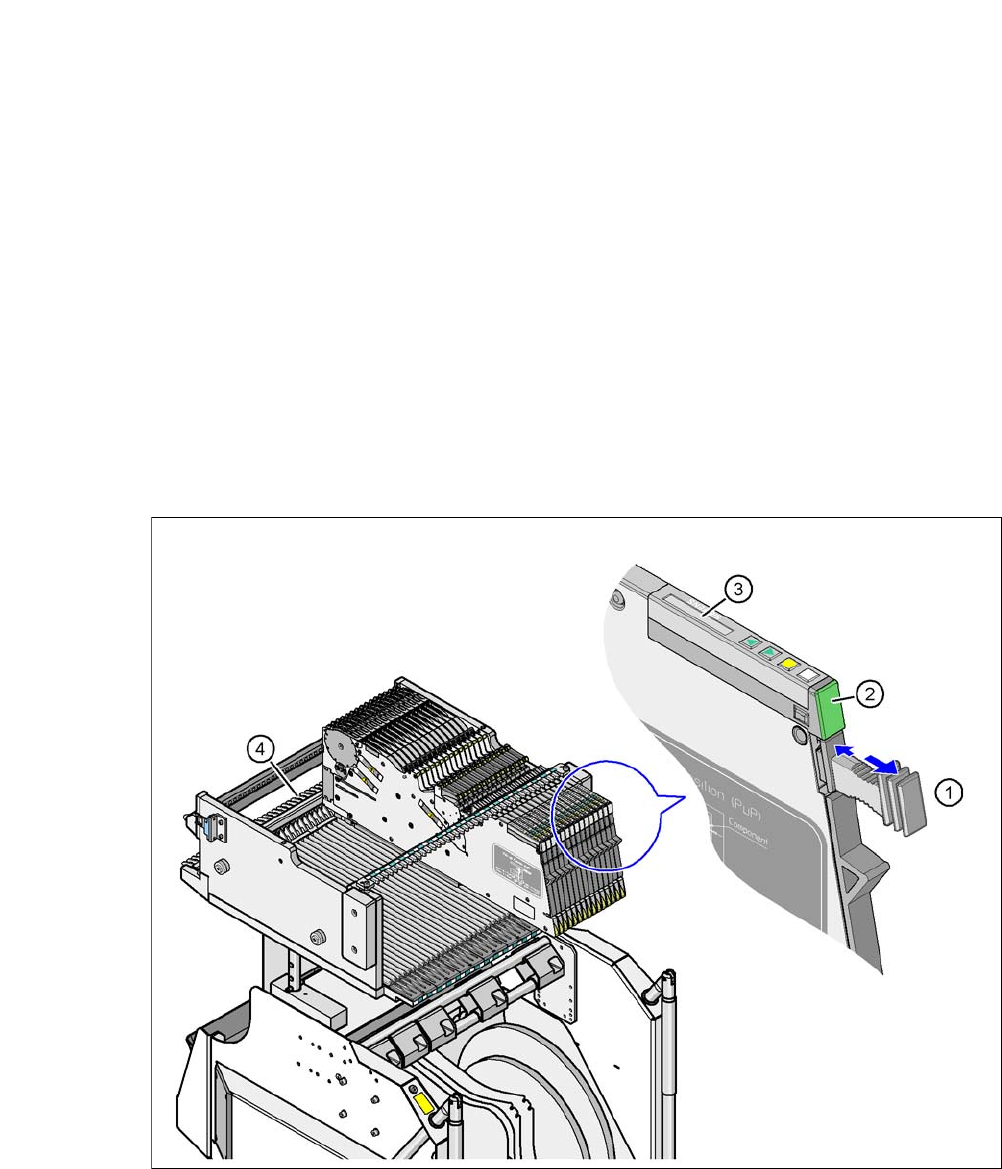
Fig. 6.7 - 1 Removing X feeder modules from the changeover table
(1) Removal handle
(2) Status display
(3) LCD display
(4) Latch for locking the X feeder modules
User Manual SIPLACE CA-Series 6 Working with the Machine
From software version SC.708.0 Edition 12/2014 EN -DRAFT 6.7 Configuring the Feeder Modules
371
On standby, the status display (item 2 in fig. 6.7 - 1) lights up green if the X axis feeder
module is contained in the current setup. If the feeder module is not contained in the current setup,
the status display remains off.
The X feeder module is locked in position in the changeover table by a latch, and cannot be pulled
out. The procedure for removing feeder modules from the changeover table is as follows:
Press the removal handle (item 1 in fig. 6.7 - 1). The removal handle jumps out and the
status display goes out.
Wait approximately 1 second until the lock (item 4 in fig. 6.7 - 1) releases the feeder mod-
ule.
Use the removal handle to pull the feeder module out of the changeover table. If you wait
longer than 5 seconds, the feeder module will be locked once more. The status display
lights up red and the message (item 3 in fig. 6.7 - 1
) on the LCD display will be "Handle
--->>".
Engage the removal handle once more. If the X feeder module is contained in the current
setup, the status display lights up green and the track number and increment are appear
on the LCD display once more.
Press the removal handle again (item 1 in fig. 6.7 - 1) and now pull the feeder
module out of the changeover table.
6.7.3 Using the X Feeder Module on the Component Trolley (X-Series)
6.7.3.1 Checking the X Feeder Module Before Use
Check the following points before you use a feeder module on the changeover table:
The feeder module must be in perfect condition.
Tap the cover foil rocker (item 2 in fig. 6.7 - 2) to make sure that it does not stick.
Check that the area around the pickup window (item 3 in fig. 6.7 - 2) is free from loose
components.
6
Press the lever (item 4 in fig. 6.7 - 2) forward slightly to open the pickup window (item 3
in fig. 6.7 - 2
). This will raise the pick-up window slightly.
6
PLEASE NOTE
Empty the component disposal compartment (item 5 in fig.6.7 - 2), before you
shake components out of the feeder module.
PLEASE NOTE
The tensioned cover foil continues to transport the tape when the tape has been inserted
and exposes the components.
Do not press the lever if a component tape is inserted.