00197498-03_UM_SiplaceCA-Serie_EN.pdf - 第185页
User Manual SIPLACE CA-Series 3 Technical Data From software version SC.708.0 Edition 12/20 14 EN -DRAFT 3.12 Vision Cameras 185 3.12.4.4 Ink Spot Criteria 3 Methods - Synthetic fiducial recognition method - Mean graysca…

3 Technical Data User Manual SIPLACE CA-Series
3.12 Vision Cameras From software version SC.708.0 Edition 12/2014 EN -DRAFT
184
3.12.4.3 Fiducial Criteria
3
Locate 2 fiducials
Locate 3 fiducials
X-/Y-position, rotation angle, mean PCB distortion
additional: shearing, distortion separately in X and Y direction
Fiducial shapes Synthetic fiducials: circle, cross, square, rectangle, diamond,
circular, square and rectangular contours, double cross
Pattern: any
Fiducial surface
Copper
Tin
Without oxidation and solder resist
Warp ≤ 1/10 of structure width, both with good contrast to
environment
Dimensions of synthetic fiducials
Min. X/Y size for circle and rectangle:
Min. X/Y size for annulus and rectangle:
Min. X/Y size for cross:
Min. X/Y size for double-cross:
Min. X/Y size for rhombus:
Min. frame width for annulus and rectangle:
Min. bar width / bar distance for cross, double-cross:
Max. X/Y size for all fiducial shapes:
Max. bar width for cross, double-cross:
Min. tolerances, general:
Max. tolerances, general:
0.25 mm
0.3 mm
0.3 mm
0.5 mm
0.35 mm
0.1 mm
0.1 mm
3 mm
1.5 mm
2% of nominal dimension
20% of nominal dimension
Dimensions of patterns
Min. size
Max. size
0.5 mm
3 mm
Fiducial environment Clearance around reference fiducial not necessary if there is no
similar fiducial structure in the search area.

User Manual SIPLACE CA-Series 3 Technical Data
From software version SC.708.0 Edition 12/2014 EN -DRAFT 3.12 Vision Cameras
185
3.12.4.4 Ink Spot Criteria
3
Methods - Synthetic fiducial recognition method
- Mean grayscale value
- Histogram method
- Template matching
Shapes and sizes of fiducials/
structures for
Synthetic fiducials
Other methods
For dimensions of synthetic fiducials see section 3.12.4.3
Fidu-
cial Criteria
Min. 0.3 mm
Max. 5 mm
Masking material Good coverage
Recognition time Depends on the method: 20 ms - 0.2s
3 Technical Data User Manual SIPLACE CA-Series
3.13 Single PCB Conveyor From software version SC.708.0 Edition 12/2014 EN -DRAFT
186
3.13 Single PCB Conveyor
[00119625-xx] Modular single conveyor II, 2380 mm
[00119626-xx] Fixed conveyor side right, HF/X/CA/D-Series
[00119628-xx] Fixed conveyor side left, HF/X/CA/D-Series
[00119629-xx] Conveyor width 250/508 mm, HF/X/CA-Series
In its standard version, the placement machine is equipped with a PCB single conveyor. The PCB
dual conveyor is available as an option ex factory (see section 3.14
, page 189). The left or the
right side of the PCB conveyor can be used as the stationary side, as required.
The conveyor belts are driven by DC motors. There is a lifting table for clamping the PCBs in each
processing area. The PCB conveyor width can either be set from the user interface or preset in
the placement program.
3.13.1 Structure
3
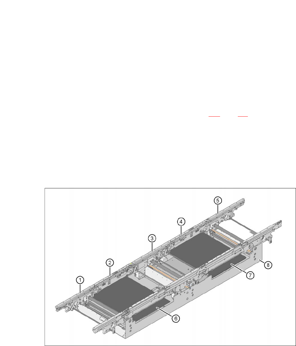
Fig. 3.13 - 1 Structure of the PCB single conveyor
(1) Input conveyor (2) Processing conveyor 1
(3) Intermediate conveyor (4) Processing conveyor 2
(5) Output conveyor (6) Lifting table 1
(7) Lifting table 2 (8) Assembly tub