00197498-03_UM_SiplaceCA-Serie_EN.pdf - 第176页
3 Technical Data User Manual SIPLACE CA-Series 3.11 Gantries From software version SC.708.0 Edition 12/2014 EN -DR AFT 176 The X axis mainly consists of the following modules: – Gantry arm (1) – Head mount with X axis li…
User Manual SIPLACE CA-Series 3 Technical Data
From software version SC.708.0 Edition 12/2014 EN -DRAFT 3.11 Gantries
175
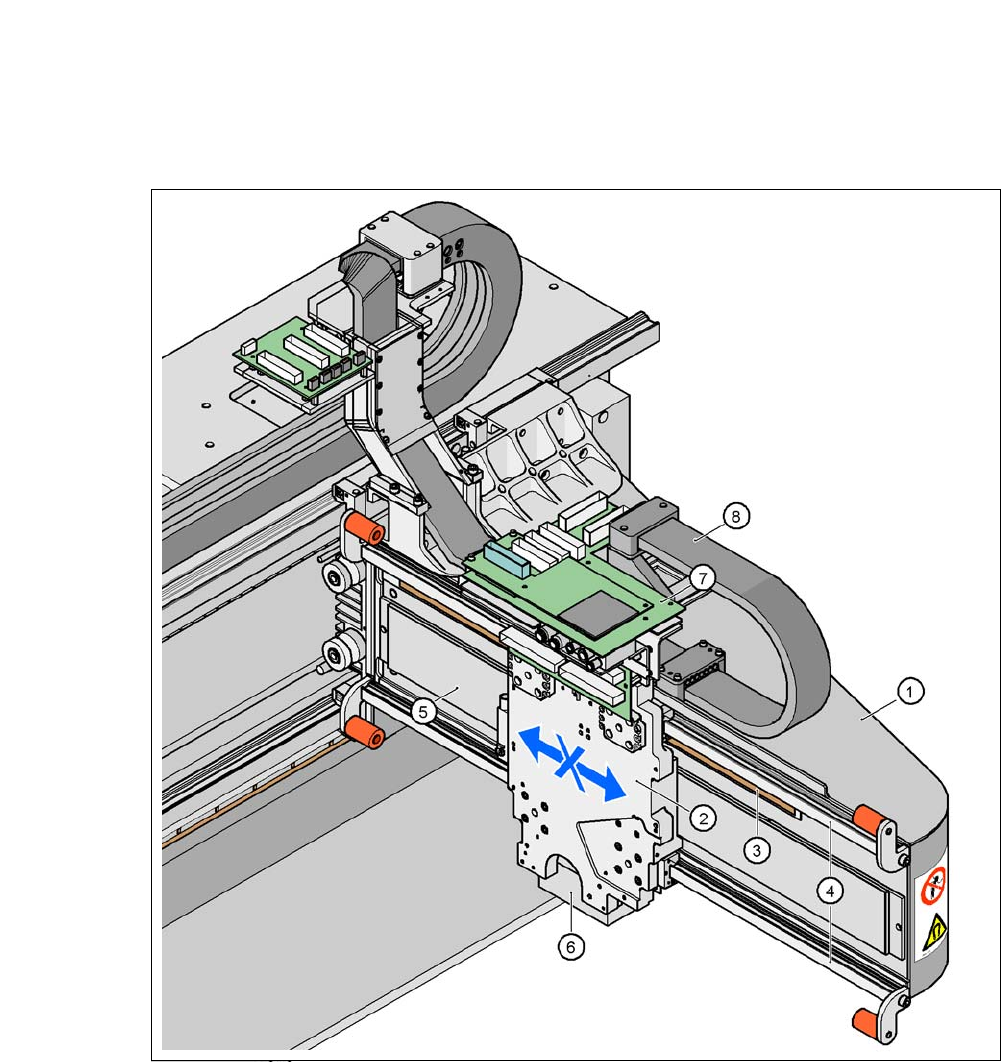
3.11.2 Structure of X Axis
3
Fig. 3.11 - 2 X axis structure
(1) Gantry arm
(2) Head mount with X axis linear motor (primary part)
(3) Linear distance measuring system
(4) Guidance system
(5) Permanent magnet (secondary part of the X axis linear motor)
(6) Sub-gantry camera
(7) Head boards
(8) Trailing cable

3 Technical Data User Manual SIPLACE CA-Series
3.11 Gantries From software version SC.708.0 Edition 12/2014 EN -DRAFT
176
The X axis mainly consists of the following modules:
– Gantry arm (1)
– Head mount with X axis linear motor (primary part) (2)
– Linear distance measuring system (3)
– Guidance system (4)
– Permanent magnet (secondary part of the X axis linear motor) (5)
– Trailing cable (8)
3
The head mount (2) takes up the following components:
– Sub-gantry camera (PCB camera of PCB Vision module) (6)
– Set of head boards (7)
– Measuring head for measuring system
– Placement head
The gantry arm (item 1 in fig. 3.11 - 2
) is made of a carbon fiber composite. This technology allows
assemblies to be made with extremely low weight and high rigidity.
The X axis is driven by a linear motor. The secondary part of the drive consists of a permanent
magnet and is mounted on the gantry arm. The primary part is bolted to the head mount. The head
mount is designed to work with all placement head types - another reason for the high flexibility
achieved with SIPLACE placement machines.
3.11.3 Technical Data for the X Axis
3
Drive Direct, linear motor
Maximum speed 2.5 m/s
Travel range 480 mm
Distance measuring system Linear metal scale
Length of scale 520 mm
Resolution 1 µm
User Manual SIPLACE CA-Series 3 Technical Data
From software version SC.708.0 Edition 12/2014 EN -DRAFT 3.11 Gantries
177
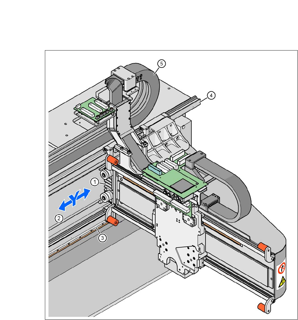
3.11.4 Structure of the Y Axis
3
Fig. 3.11 - 3 Y axis structure
(1) Y linear motor (primary part)
(2) Permanent magnet (secondary part of the Y axis linear motor)
(3) Linear distance measuring system
(4) Guidance system
(5) Trailing cable