00197498-03_UM_SiplaceCA-Serie_EN.pdf - 第151页
User Manual SIPLACE CA-Series 3 Technical Data From software version SC.708.0 Edition 12/20 14 EN -DRAFT 3.7 Placement Heads 151 3.7.1.4 T echnical Dat a 3 3.7.1.5 Sensor for the Compone nt Reject Bin 3 SIPLACE SpeedStar…

3 Technical Data User Manual SIPLACE CA-Series
3.7 Placement Heads From software version SC.708.0 Edition 12/2014 EN -DRAFT
150
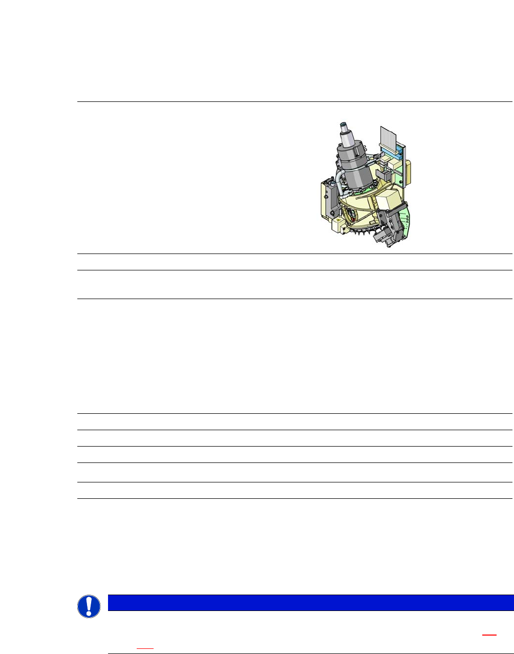
Component Camera (item. 1 in fig. 3.7 - 2) 3
The component camera is fitted to the placement head at star position 11 (item 11 in fig. 3.7 - 3).
It uses a digital interface (hotlink) to exchange data with the vision processor in the axis unit. The
camera is designed to capture the component from underneath. If a component drops onto the
camera, it is removed from the camera field via a removal ramp.
Intermediate Distributor (item 2 in fig. 3.7 - 2) 3
The adapter board is the interface between placement head and placement machine. The vacuum
sensor for the holding circuit is mounted on the star housing.
The following functions are implemented on the adapter board:
– Display the operating voltages at the head
– Display the sensor statuses
– Test access to the CAN bus for the placement head
– Test connector for the signals from the incremental encoder
– Test pins for the analog signals
– Control of the power supply for the incremental encoders for the star and Z drives
– SPI bus interface for the component sensor, the vacuum unit, the "Holding circuit" vac-
uum sensor and the EEPROM
– Signal processing for the output signal from the "Holding circuit" vacuum sensor
– Signal processing for the component sensor signal
– Signal processing for the "Z axis down" sensor
– Signal processing for the CAN bus for the placement head and the machine
– Control of return cylinder for the Z axis
User Manual SIPLACE CA-Series 3 Technical Data
From software version SC.708.0 Edition 12/2014 EN -DRAFT 3.7 Placement Heads
151
3.7.1.4 Technical Data
3
3.7.1.5 Sensor for the Component Reject Bin
3
SIPLACE SpeedStar (C&P 20 M)
with component camera type 41
Component range
*a
*)a Please note that the placeable component range is also affected by the pad geometry, the customer-specific
standards, the component packaging tolerances and the component tolerances.
03015 to 2220, Melf, SOT, SOD,
Bare-Die, Flip-Chip
Component spec.
Max. height
Min. lead pitch
Min. lead width
Min. ball pitch
Min. ball diameter
Min. dimensions
Max. dimensions
Max. weight
4 mm
0.08 mm
0.03 mm
0.10 mm
0.05 mm
0.3 mm x 0.15 mm
6 mm x 6 mm
1 g
Programmable set-down force 1.5 - 4.5 N
Nozzle types 10xx, 11xx, 12xx
X/Y accuracy (SMT) ± 20 µm / 3σ
X/Y accuracy (CA)
*b
*)b 10µm at 3
σ in placement process; Option eWLB on request.
± 10 µm / 3σ
Angular accuracy ± 0.2° / 3σ
PLEASE NOTE
When using a SIPLACE SpeedStar (C&P20 M) at a location without SWS, we recommend
that you install the optional sensor for the component reject bin. (See also section 8.2
,
page 473
)
3 Technical Data User Manual SIPLACE CA-Series
3.7 Placement Heads From software version SC.708.0 Edition 12/2014 EN -DRAFT
152
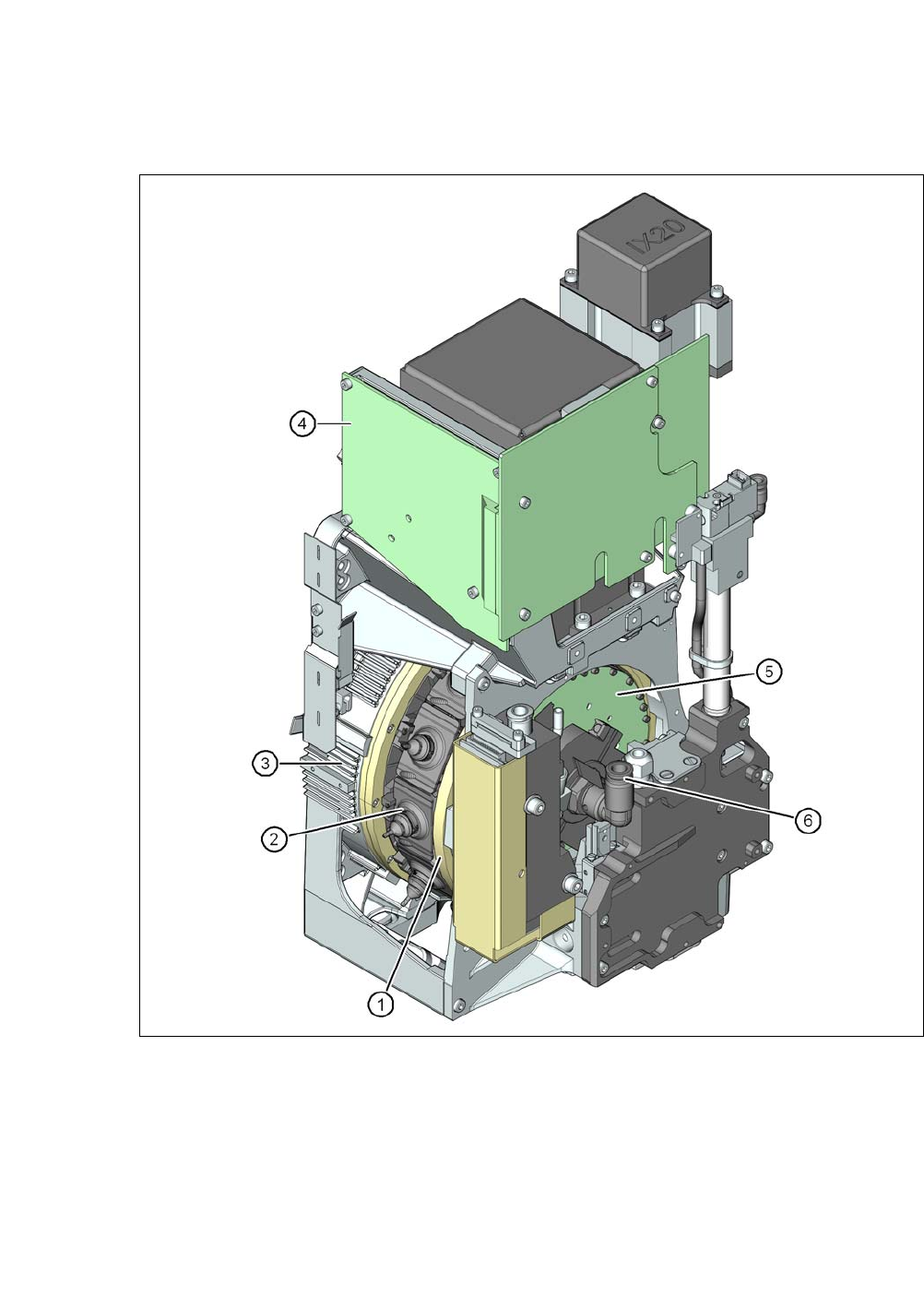
3.7.2 SIPLACE MultiStar
3
Fig. 3.7 - 4 SIPLACE MultiStar - front view, function groups part 1
(1) Star with 12 segments
(2) Segment with integrated DP drive
(3) Torque motor for star drive
(4) Intermediate distributor board
(5) Control board for 12 DP drives
(6) Compressed air connection for the Venturi nozzles in the pickup/placement and holding cir-
cuit