00197498-03_UM_SiplaceCA-Serie_EN.pdf - 第279页
User Manual SIPLACE CA-Series 5 Setting up and Commissioning From software version SC.708.0 Edition 12/20 14 EN -DRAFT 5.5 Setting Up the Placement Machine 279 5.5 Setting Up the Placement Machine 5.5.1 PCB Conveyor Heig…
5 Setting up and Commissioning User Manual SIPLACE CA-Series
5.4 Infrastructure at the Installation Location From software version SC.708.0 Edition 12/2014 EN -DRAFT
278
5
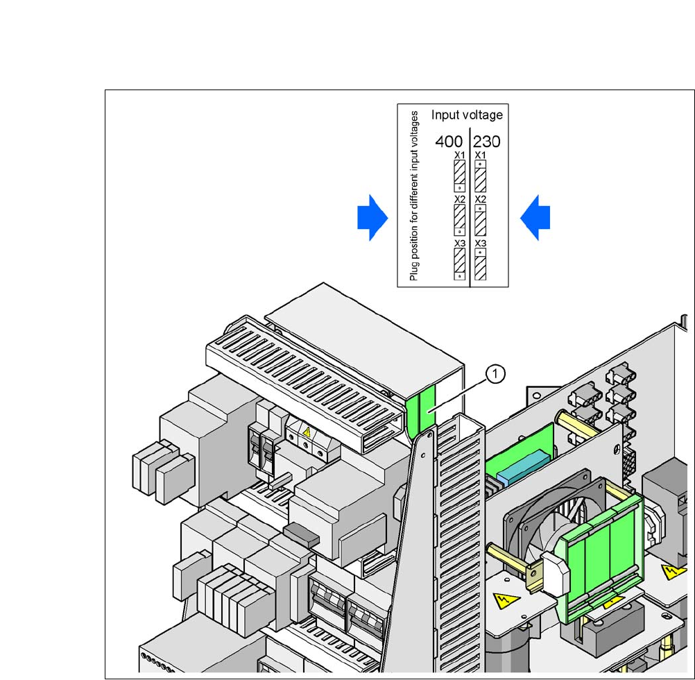
Fig. 5.4 - 5 Position of the board and connectors for the inrush current limitation
5
(1) Inrush current limitation board
X1, X2, X3 Connectors for configuring the inrush current limitation on the board
Check the jumper assignment and correct if necessary.
3 x 380 VAC
3 x 400 VAC
3 x 415 VAC
3 x 208 VAC
3 x 230 VAC
User Manual SIPLACE CA-Series 5 Setting up and Commissioning
From software version SC.708.0 Edition 12/2014 EN -DRAFT 5.5 Setting Up the Placement Machine
279
5.5 Setting Up the Placement Machine
5.5.1 PCB Conveyor Height for Placement Machine
The machine can be set to the following PCB conveyor heights:
900 mm ± 15 mm 5
930 mm ± 15 mm (standard height) 5
950 mm ± 15 mm (SMEMA height) 5
5
5.5.2 Warning Instructions
5
5
5
PLEASE NOTE
The PCB conveyor height is the distance between the top edge of the PCB conveyor belt
and the bottom edge of the machine feet.
WARNING
Observe the applicable accident prevention regulations!
Only ASM engineers or qualified people are permitted to set up and commission the place-
ment machine.
Always follow the applicable accident prevention regulations.
WARNING
Risk of injury during assembly work to the underside of the machine!
All assemblies and parts can be accessed for fitting from the space for the changeover
tables. There is a risk of injury during assembly work to the underside of the machine!
When fitting the machine feet, never lie down under the placement machine.
Secure the machine using suitable measures. The fork-lift must not be used as the
only support.
WARNING
Risk of injury during assembly work!
Incorrect positioning of gantries during assembly restricts the head clearance and could
lead to injuries.
Take care that the gantries are positioned over the board conveyor area.
5 Setting up and Commissioning User Manual SIPLACE CA-Series
5.5 Setting Up the Placement Machine From software version SC.708.0 Edition 12/2014 EN -DRAFT
280
5
5
5.5.3 Tools and Equipment
You will need the following tools and equipment to adjust the height of the placement machine:
– Fork wrench SW 36 [00096286-01]
Wrench of width 36 for the setting screw M24x2x120 used to adjust the height of the ma-
chine feet. 5
– Hook wrench 135 - 145 for adjusting the middle machine feet [00376519-xx]
– Single head wrench SW 65 [00353827-01]
Size 65 for the hexagon lock nut M24 on the middle machine foot 5
– Allen keys, size 10 [00373926-01]
for hexagon socket head screws M12x80 for fixing the spacers for the middle machine feet5
– Allen keys, size 19 [00373928-01]
for hexagon socket head screw M24x90 for temporarily clamping the four outer machine
feet clamps 5
– Torque wrench with hexagonal pin, size 19, tightening torque 130 Nm
for final fastening of four outer machine feet
– Fork lift truck
Fork length: Min. 1,800 mm 5
Lifting power: Min. 6,000 kg 5
Width between forks: See fig. 5.5 - 1
5
– Machine spirit level: accuracy 0.02 mm/m
– Air cushion transport system: SIPLACE HSxx [00119002-xx]
WARNING
Height adjustment of machine!
Two people will be needed to adjust the height of the machine:
– One person completes the required assembly work
– The other person watches the stability of the raised placement machine during
assembly.
WARNING
DANGER OF CRUSHING!
One machine foot weighs 6.75 kg. There is a risk of crushing your feet when transporting
the machine.
Wear specially reinforced shoes.