00197498-03_UM_SiplaceCA-Serie_EN.pdf - 第165页
User Manual SIPLACE CA-Series 3 Technical Data From software version SC.708.0 Edition 12/20 14 EN -DRAFT 3.8 Electrical and Pneumatic Connections 165 3.8 Electrical and Pneumatic Connections 3.8.1 Electrical Connect ion …
3 Technical Data User Manual SIPLACE CA-Series
3.7 Placement Heads From software version SC.708.0 Edition 12/2014 EN -DRAFT
164
3.7.3.2 Technical Data
SIPLACE TwinStar
*a
With component camera type 33
(fine pitch camera)
With component camera type 25
(flip chip camera)
Component range
*b
0402 to SO, PLCC, QFP, BGA, special compo-
nents, bare dies, flip-chips
0201 to SO, PLCC, QFP, sockets,
plugs, BGA, special components, bare
dies, flip-chips, shields
Component specs
*c
Max. height
Min. lead pitch
Min. lead width
Min. ball pitch
Min. ball diameter
Min. dimensions
Max. dimensions
Max. weight
*d
25 mm (higher available on request)
0.3 mm
0.15 mm
0.35 mm
0.2 mm
1.0 mm x 0.5 mm
55 mm x 45 mm (single measurement)
For use with two nozzles (multiple measurement)
50 mm x 50 mm or
69 mm x 10 mm
For use with one nozzle
85 mm x 85 mm or
125 mm x 10 mm
up to 200 mm x 125 mm (with restrictions)
100 g
25 mm (higher available on request)
0.25 mm
0.1 mm
0.14 mm
0.08 mm
0.6mm x 0.3mm
16 mm x 16 mm (single measurement)
55 mm x 55 mm (multiple measure-
ment)
100 g
Programmable set-down
force
1.0 N - 15 N
2.0 N - 30 N
*e
1.0 N - 15 N
2.0 N - 30 N
d
Nozzle types
*f
5xx (standard)
4xx + adapter
8xx + adapter
9xx + adapter
Gripper
5xx (standard)
4xx + adapter
8xx + adapter
9xx + adapter
Gripper
Nozzle spacing for P&P
heads
70.8 mm 70.8 mm
X/Y accuracy
*g
± 26 µm / 3σ, ± 35 µm / 4σ ± 22 µm / 3σ, ± 30 µm / 4σ
Angular accuracy ± 0.05° / 3σ, ± 0.07°/ 4σ ± 0.05° / 3σ, ± 0.07° / 4σ
Illumination level 6 6
Possible illumination level
settings
256
6
256
6
*)a Not in conjunction with SWS and not on location 2/4.
*)b Please note that the placeable component range is also affected by the pad geometry, the customer-specific standards, the com-
ponent packaging tolerances and the component tolerances.
*)c If the MultiStar and TwinStar are combined in the same placement area, the maximum component height may be restricted .
*)d If standard nozzles are used
*)e SIPLACE High-Force Head.
*)f Over 300 different nozzles and 100 gripper types are available, with an extensive nozzle database available online.
*)g The SIPLACE benchmark value is measured during the machine acceptance tests. It corresponds to the conditions set out in the
SIPLACE scope of service and supply.
User Manual SIPLACE CA-Series 3 Technical Data
From software version SC.708.0 Edition 12/2014 EN -DRAFT 3.8 Electrical and Pneumatic Connections
165
3.8 Electrical and Pneumatic Connections
3.8.1 Electrical Connection (Placement Machine)
3
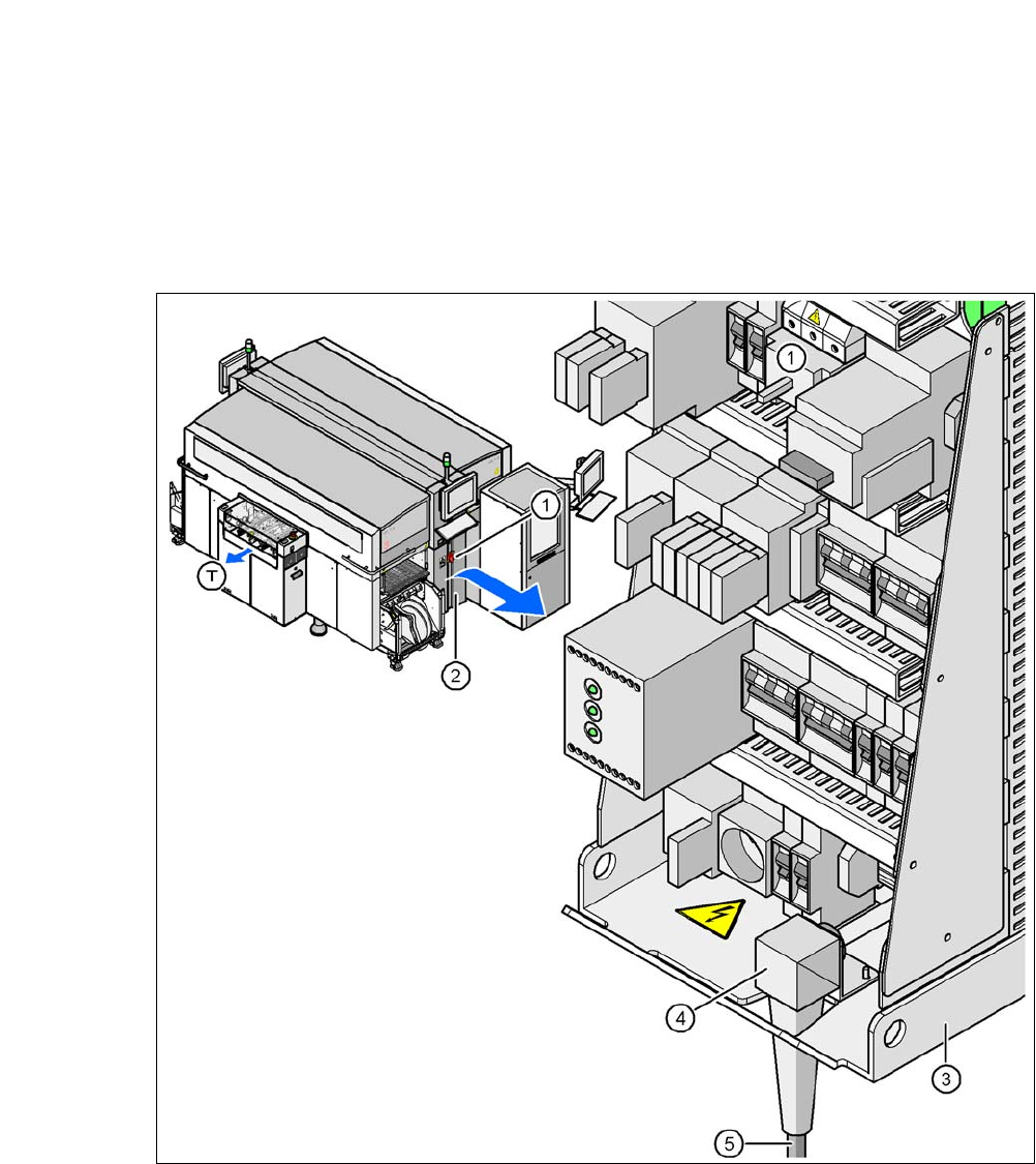
Fig. 3.8 - 1 Electrical connection on the placement machine
(1) Main switch
(2) Cover above the power supply unit
(3) Power supply unit
(4) Angled cable gland
(5) Mains connection cable
(T) Direction of PCB transport
3 Technical Data User Manual SIPLACE CA-Series
3.8 Electrical and Pneumatic Connections From software version SC.708.0 Edition 12/2014 EN -DRAFT
166
3.8.2 Pneumatic Connection on the Placement Machine
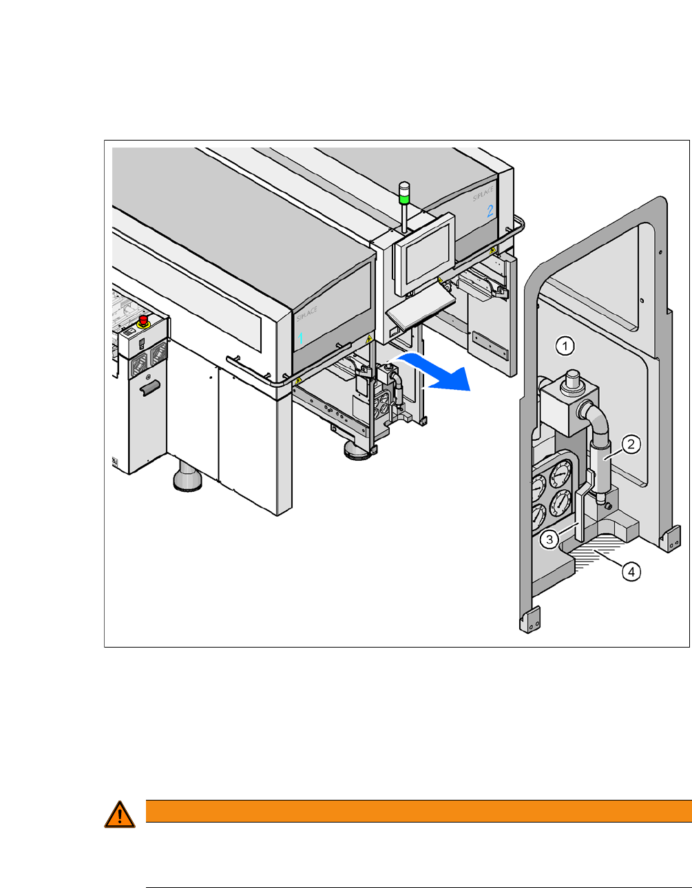
Fig. 3.8 - 2 Pneumatic Connection on the Placement Machine
(1) Pneumatic unit
(2) Connection coupling for the compressed air hose
(3) Shutoff valve
(4) Cutoff for the pneumatic hose
3
WARNING
Risk of injuries!
Risk of injuries from pressurized compressed air lines.
NEVER detach compressed air lines while they are still pressurized.