00197498-03_UM_SiplaceCA-Serie_EN.pdf - 第278页
5 Setting up and Commissioning User Manual SIPLACE CA-Series 5.4 Infrastructure at the Installation Location From software version SC.708.0 Edition 12/2014 EN -DRAFT 278 5 Fig. 5.4 - 5 Position of the board and connec to…

User Manual SIPLACE CA-Series 5 Setting up and Commissioning
From software version SC.708.0 Edition 12/2014 EN -DRAFT 5.4 Infrastructure at the Installation Location
277
Crimp a ferrule onto each end of the wire.
Loosen the nut on the angled cable gland (item 2 in fig. 5.4 - 3).
Fold up the angled cable gland.
Run the power supply cable through the angled cable gland and to the terminal panel X100
(see X100 in fig. 5.4 - 4
).
Connect the cable to the terminal and ensure that it has a sufficient bending radius. The wires
must not be kinked.
Close the angled cable gland (item 2 in fig. 5.4 - 3) and hand-tighten the nut.
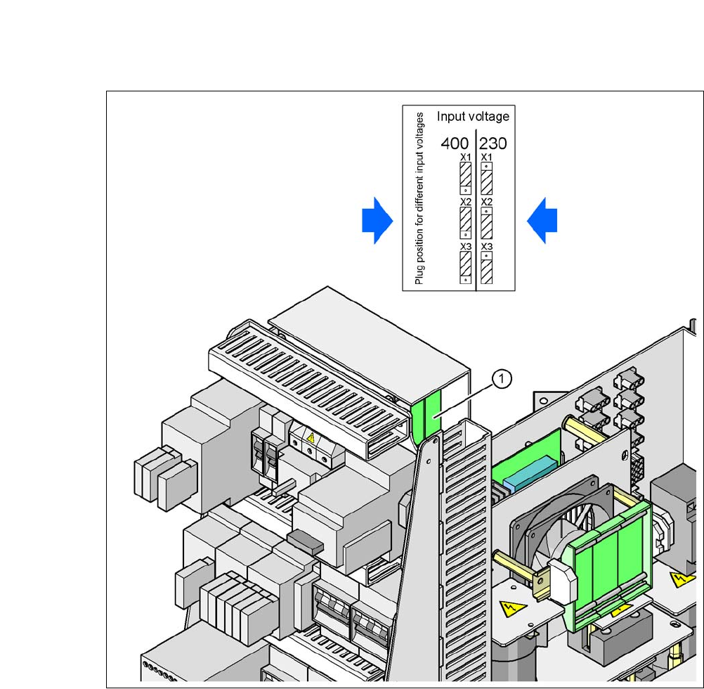
5.4.4.5 Checking the Inrush Current Limitation Jumpers
The inrush current limitation must be configured in relation to the supply voltage. This is achieved
with the help of plug-in bridges on the inrush current limitation board (item 1 in fig. 5.4 - 5
).
5 Setting up and Commissioning User Manual SIPLACE CA-Series
5.4 Infrastructure at the Installation Location From software version SC.708.0 Edition 12/2014 EN -DRAFT
278
5
Fig. 5.4 - 5 Position of the board and connectors for the inrush current limitation
5
(1) Inrush current limitation board
X1, X2, X3 Connectors for configuring the inrush current limitation on the board
Check the jumper assignment and correct if necessary.
3 x 380 VAC
3 x 400 VAC
3 x 415 VAC
3 x 208 VAC
3 x 230 VAC
User Manual SIPLACE CA-Series 5 Setting up and Commissioning
From software version SC.708.0 Edition 12/2014 EN -DRAFT 5.5 Setting Up the Placement Machine
279
5.5 Setting Up the Placement Machine
5.5.1 PCB Conveyor Height for Placement Machine
The machine can be set to the following PCB conveyor heights:
900 mm ± 15 mm 5
930 mm ± 15 mm (standard height) 5
950 mm ± 15 mm (SMEMA height) 5
5
5.5.2 Warning Instructions
5
5
5
PLEASE NOTE
The PCB conveyor height is the distance between the top edge of the PCB conveyor belt
and the bottom edge of the machine feet.
WARNING
Observe the applicable accident prevention regulations!
Only ASM engineers or qualified people are permitted to set up and commission the place-
ment machine.
Always follow the applicable accident prevention regulations.
WARNING
Risk of injury during assembly work to the underside of the machine!
All assemblies and parts can be accessed for fitting from the space for the changeover
tables. There is a risk of injury during assembly work to the underside of the machine!
When fitting the machine feet, never lie down under the placement machine.
Secure the machine using suitable measures. The fork-lift must not be used as the
only support.
WARNING
Risk of injury during assembly work!
Incorrect positioning of gantries during assembly restricts the head clearance and could
lead to injuries.
Take care that the gantries are positioned over the board conveyor area.