00197498-03_UM_SiplaceCA-Serie_EN.pdf - 第392页
6 Working with the Machine User Manual SIPLACE CA-Series 6.15 Observing the Indicator Lamps for Operating State s From software version SC.708.0 Edition 12/2014 EN -DRAFT 392 6.15 Observing the Indicator Lamp s for Opera…
User Manual SIPLACE CA-Series 6 Working with the Machine
From software version SC.708.0 Edition 12/2014 EN -DRAFT 6.14 Docking/Undocking the Component Trolley
391
6
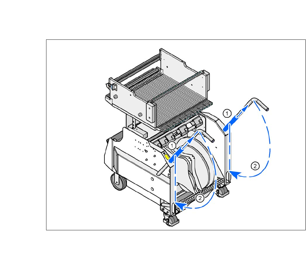
Fig. 6.14 - 4 X-Series component trolley - swivel handles down
(1) Push sleeve up
(2) Fold handle down
6 Working with the Machine User Manual SIPLACE CA-Series
6.15 Observing the Indicator Lamps for Operating States From software version SC.708.0 Edition 12/2014 EN -DRAFT
392
6.15 Observing the Indicator Lamps for Operating
States
The indicator lamp signals operating machine operating states and malfunctions.
6.15.1 Functions
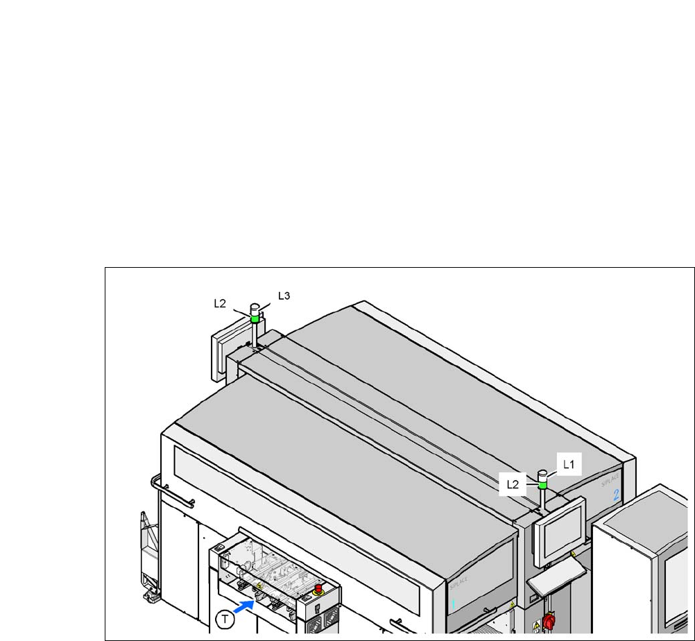
Fig. 6.15 - 1 Operating status indicator lamp
L1 Indicator lamp (white, right)
L2 Operating status indicator lamp (green, both lamps switched parallel)
L3 Fault indicator lamp (white, left)
T Direction of PCB transport

User Manual SIPLACE CA-Series 6 Working with the Machine
From software version SC.708.0 Edition 12/2014 EN -DRAFT 6.15 Observing the Indicator Lamps for Operating States
393
6.15.2 General Operating States
– Operating status indicator lamp L2 (green) on continuously
The placement system is in service.
– Operating status indicator lamp L2 (green) flashes
The placement system is waiting for a PCB on the input belt or the placement system is wait-
ing until the output belt is free.
– Right fault indicator lamp L1 (white) flashes
One or more tracks are empty on the right-hand side of the placement system. The placement
system continues to place any remaining components.
– Left fault indicator lamp L3 (white) flashes
One or more tracks are empty on the left-hand side of the placement system. The placement
system continues to place any remaining components.
– Right fault indicator lamp L1 (white ) on continuously - operating status lamp L2 (green) off
An error has occurred on the right-hand side of the placement system -> the placement sys-
tem has stopped.
– Left fault indicator lamp L3 (white ) on continuously - operating status lamp L2 (green) off
An error has occurred on the left-hand side of the placement system -> the placement system
has stopped.
– Both fault indicator lamps L1 and L3 (white ) on continuously - operating status lamp L2
(green) off
An error has occurred on the whole machine-> the placement machine has stopped.
6.15.3 Programmed Operating Status Displays
The following table shows the programmed operating status displays in the standard configuration
(version as supplied) and lists their meaning on the individual lamps of the main fault indicator.
The entries in the table next to "flashes" refer to the frequency with which the relevant lamp flashes
for a given event. The entry (1, 5), for example, can be explained as follows:
– The first number in the brackets indicates the time, expressed in 100 ms intervals, for which
the fault indicator lamp is switched on, i.e. 1 x 100 ms in the above example.
– The second number in the brackets indicates the time, expressed in 100 ms intervals, for
which the fault indicator lamp is switched off, i.e. 5 x 100 ms in the above example.
6
L1 (white)
(right lamp)
L2 (green) L3 (white)
(left lamp)
Meaning
Operating state
flashes (1,10) flashes (7,7) flashes (1,10) Reference run
unchanged flashes (1,5) unchanged Waiting until axes in position