00197498-03_UM_SiplaceCA-Serie_EN.pdf - 第236页
4 SIPLACE Wafer System (SWS) User Manual SIPLACE CA- Series 4.5 SIPLACE SWS Wafer Stretcher From software version SC.708.0 Edition 12/2014 236 4.5.1 Safety Instructions 4 4 Fig. 4.5 - 2 Wafer support with SIPLACE SWS Waf…
User Manual SIPLACE CA-Series 4 SIPLACE Wafer System (SWS)
From software version SC.708.0 Edition 12/2014 4.5 SIPLACE SWS Wafer Stretcher
235
4.5 SIPLACE SWS Wafer Stretcher
The SIPLACE Wafer System (SWS) can be configured with the SIPLACE SWS Wafer Stretcher
option for two different wafer supports (8" or 12").
The SIPLACE SWS Wafer Stretcher consists of the following main assemblies.
– Stretcher
The stretcher stretches the wafer foil to increase the distances of the dies on it. 4
–Heater
The heater consists of a heating element and a fan. The fan blows heated air on to the wafer
foil. This reduces the sag of the wafer foil (less than 9 mm), so that the wafer can be trans-
ported back into the magazine. 4
4
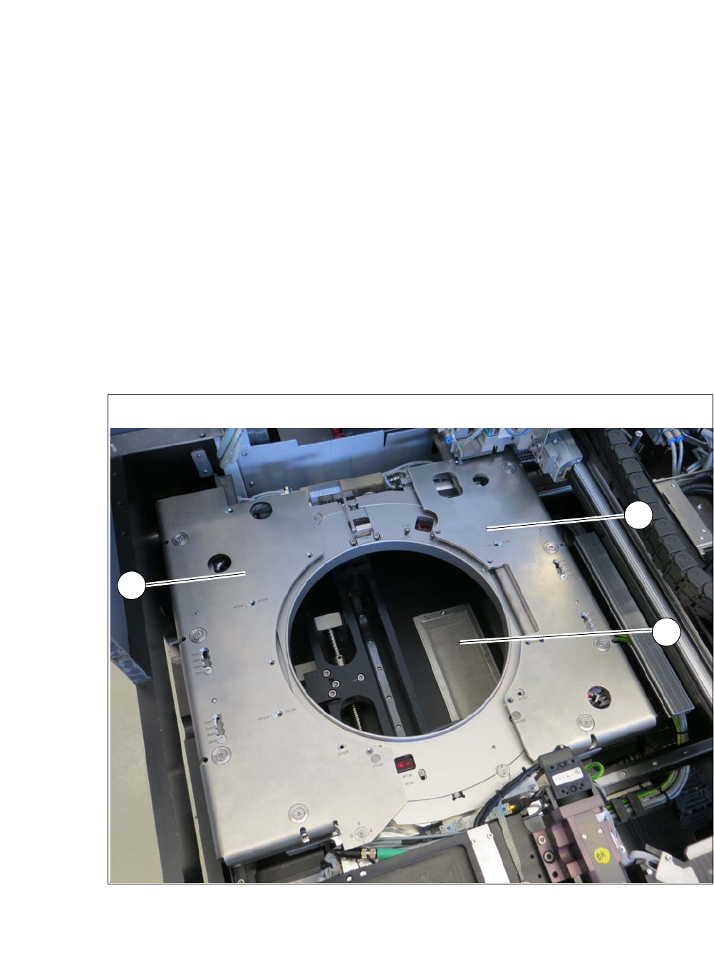
Fig. 4.5 - 1 Wafer support with SIPLACE SWS Wafer Stretcher
(1) Stretcher frame with wafer support
(2) Heater fan
2
1
1
4 SIPLACE Wafer System (SWS) User Manual SIPLACE CA-Series
4.5 SIPLACE SWS Wafer Stretcher From software version SC.708.0 Edition 12/2014
236
4.5.1 Safety Instructions
4
4
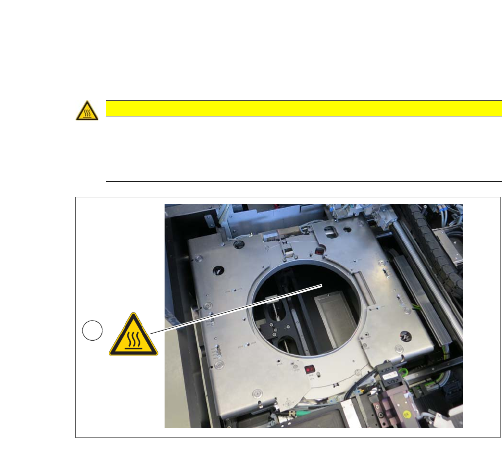
Fig. 4.5 - 2 Wafer support with SIPLACE SWS Wafer Stretcher
4
CAUTION
Risk of burns due to high temperatures!
The heating can reach temperatures of up to 60°C.
Do not reach into the area around the fan with your hands.
Be careful when touching the wafer support.
1
User Manual SIPLACE CA-Series 4 SIPLACE Wafer System (SWS)
From software version SC.708.0 Edition 12/2014 4.5 SIPLACE SWS Wafer Stretcher
237
4.5.2 Technical Data
4
4
4.5.3 Placement Accuracy and Performance Values
See also the specifications for SIPLACE CA-Series, SC 708.0, edition 12/2014
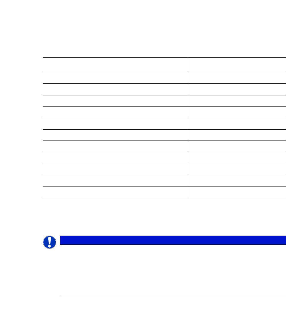
SIPLACE SWS Wafer Stretcher
Value
Wafer frame 8" or 12"
Wafer width for 8" wafer frame 10.5 " and 10.8"
Weight of stretcher with wafer support 8 " 14 kg
Weight of stretcher with wafer support 12 " 15 kg
Wafer frame (metal and plastic) Up to 3.5 mm thick
Minimum operating pressure 4.0 bar
Maximum operating pressure 5.5 bar
Travel time whole stroke Approx. 2 seconds
Lowering time Approx. 2 seconds
Stretching factor (adjustable)
*1
*)1The specified stretching factors relate to a wafer frame with a thickness of 1.5 mm. The following applies to
other wafer frame thicknesses:
Stretching factor = set stretch height + frame thickness -1.5 mm
2 mm, 4 mm, 6 mm, 8 mm
Clamping speed wafer centering 0.5 to 1.0 seconds
PLEASE NOTE
Definition
Extensive tests with various materials are conducted during the product development
phase.
However, due to the multitude of wafer foils available, the many die sizes and wafer
frames, we are unable to make a general function promise for all imaginable materials.
New materials should therefore be tested in advance, if there is any doubt